EFD1000 Installation Manual
DOCUMENT # A-01-126-00 PAGE 186-225 Revision H
© Copyright 2009 Aspen Avionics Inc.
basemap symbols underlay all other instruments and annunciations in the lower half of
the display. Map and flight plan elements are received from the GPS, and are only
available when connected to a compatible GPS unit (i.e., Garmin GNS4xx/5xx).
The base map is always oriented with magnetic heading up and centered so that the
current aircraft position coincides with the aircraft own ship symbol.
Map Features
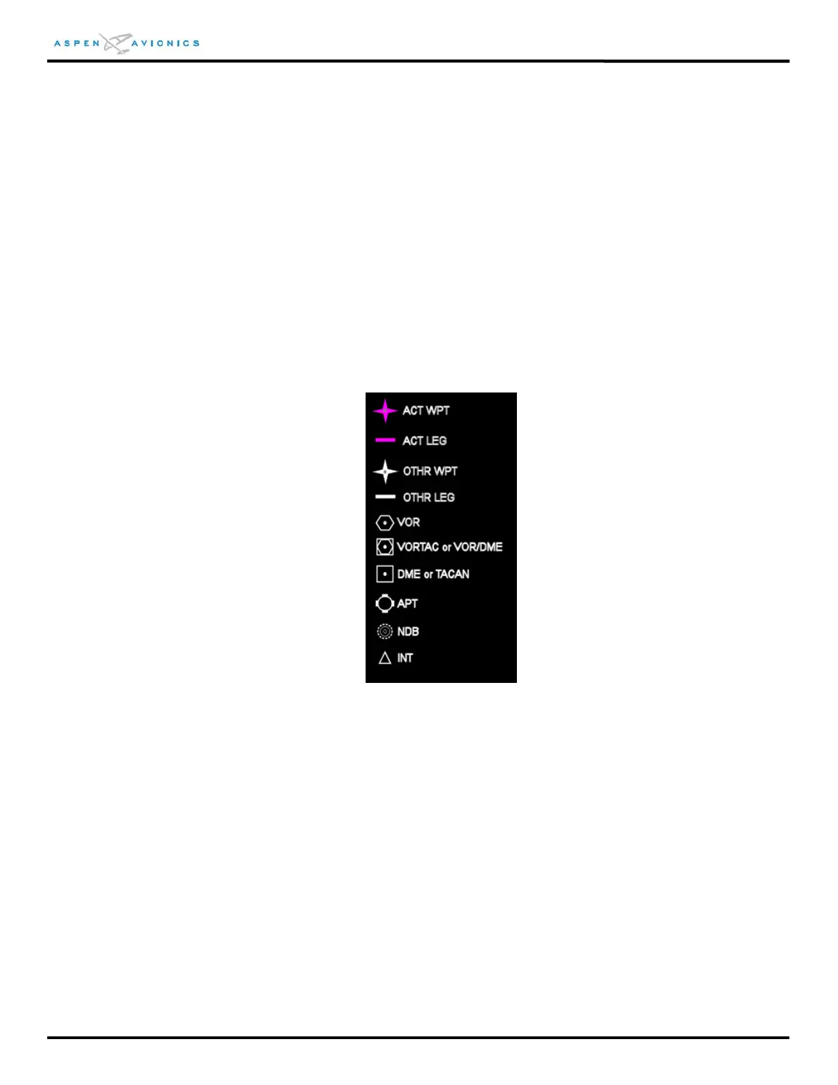
When available, flight plan waypoints, airports, VORs, DMEs, NDBs, and intersection
symbols are rendered as shown in Figure 12.30 below. Map feature identifiers, when
displayed, are shown adjacent to their associated symbol.
Figure 12.30 – Map Feature Identifiers
Flight Plan
When a flight plan is received from a compatible GPS system the Basemap will show the
current and future flight plan waypoints and legs. The active leg waypoint and its
associated identifier are displayed in magenta. Other waypoints and legs are white.
Depending on the range and selected feature display level, waypoint identifiers are
displayed adjacent to their associated waypoints.
Flight plan depictions are rotated within the display to maintain their correct compass
orientations at all times.