EFD1000 Installation Manual
DOCUMENT # A-01-126-00 PAGE 223-225 Revision H
© Copyright 2009 Aspen Avionics Inc.
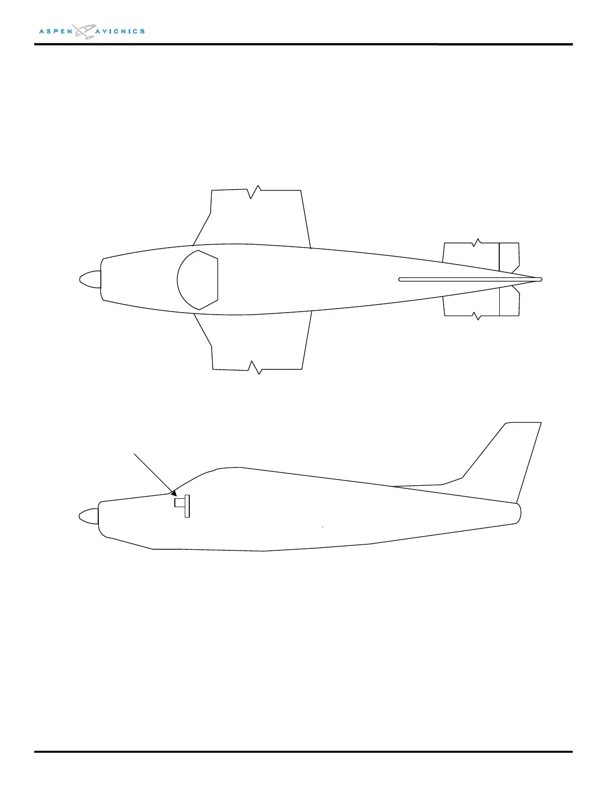
INSTRUCTIONS:
1. Draw in RSM and optional ACU and autopilot locations as done for PFD below.
2. Draw in circuit breaker locations.
3. Draw in PFD to RSM cable routing.
4. Draw in ACU to PFD and ACU to autopilot cable routing.
A
Figure D1 – LRU and cable routing diagram
LRU and Circuit Breaker Definitions
A) PFD (CM is wired within 12” of PFD) E) PFD circuit breaker location
B) RSM F) ACU#1 circuit breaker location - optional
C) ACU#1 – optional G) ACU#2 circuit breaker location – optional
D) ACU#2 – optional H) Autopilot computer location
 Loading...


