EFD1000 Installation Manual
DOCUMENT # A-01-126-00 PAGE 87-225 Revision H
© Copyright 2009 Aspen Avionics Inc.
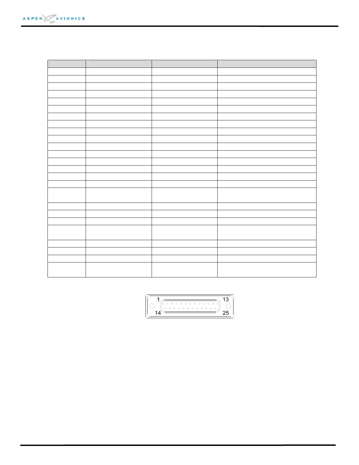
Pin Number Name Input / Output Function
J3-1 429RX1A INPUT ARINC 429 Port 1 Receive A
J3-2 429TX1A OUTPUT ARINC 429 Port 1 Transmit A
J3-3 CRS-DATUM OUTPUT Course Datum output
J3-4 429TX2A OUTPUT ARINC 429 Port 2 Transmit A
J3-5 429TX2B OUTPUT ARINC 429 Port 2 Transmit B
J3-6 OBS SIN - OUTPUT Sin of selected course angle (L)
J3-7 OBS COS - OUTPUT Cos of selected course angle (L)
J3-8 ROTOR C OUTPUT OBS sin/cos excitation (L)
J3-9 +15V-EXT-OUT OUTPUT Internal +15Vdc reference
J3-10 SIGNAL-COM - Signal ground
J3-11 HDG/CRS-COM - Signal ground
J3-12 Reserved - Reserved
J3-13 Reserved - Reserved
J3-14 429RX1B INPUT ARINC 429 Port 1 Receive B
J3-15 429TX1B OUTPUT ARINC 429 Port 1 Transmit B
J3-16 SIGNAL-COM - Signal ground
J3-17 GPS SELECTED
OUTPUT Active Low signal to drive GPS and
Autopilot inputs.
J3-18 OBS SIN + OUTPUT Cos of selected course angle (H)
J3-19 OBS COS + OUTPUT Sin of selected course angle(H)
J3-20 ROTOR H INPUT OBS sin/cos excitation (H)
J3-21 ARINC-HDG-CRS-EXT
- 26Vac reference to emulate an ARINC
synchro interface
J3-22 HDG-DATUM OUTPUT Heading Datum output
J3-23 HDG-CRS-DATUM-EXT INPUT Heading/Course Datum excitation input
J3-24 Reserved - Reserved
J3-25 HDG-CRS-OFST
INPUT Heading/Course Datum excitation
offset input
Figure 8.6 - J3 Connector (as viewed from front of unit)