EFD1000 Installation Manual
DOCUMENT # A-01-126-00 PAGE 93-225 Revision H
© Copyright 2009 Aspen Avionics Inc.
Over Braid or
Double Shield
Over Braid or
Double Shield
EFD1000
8
RS-232 IN
P1
P891
P941
P901 P9002
5
2
13
6
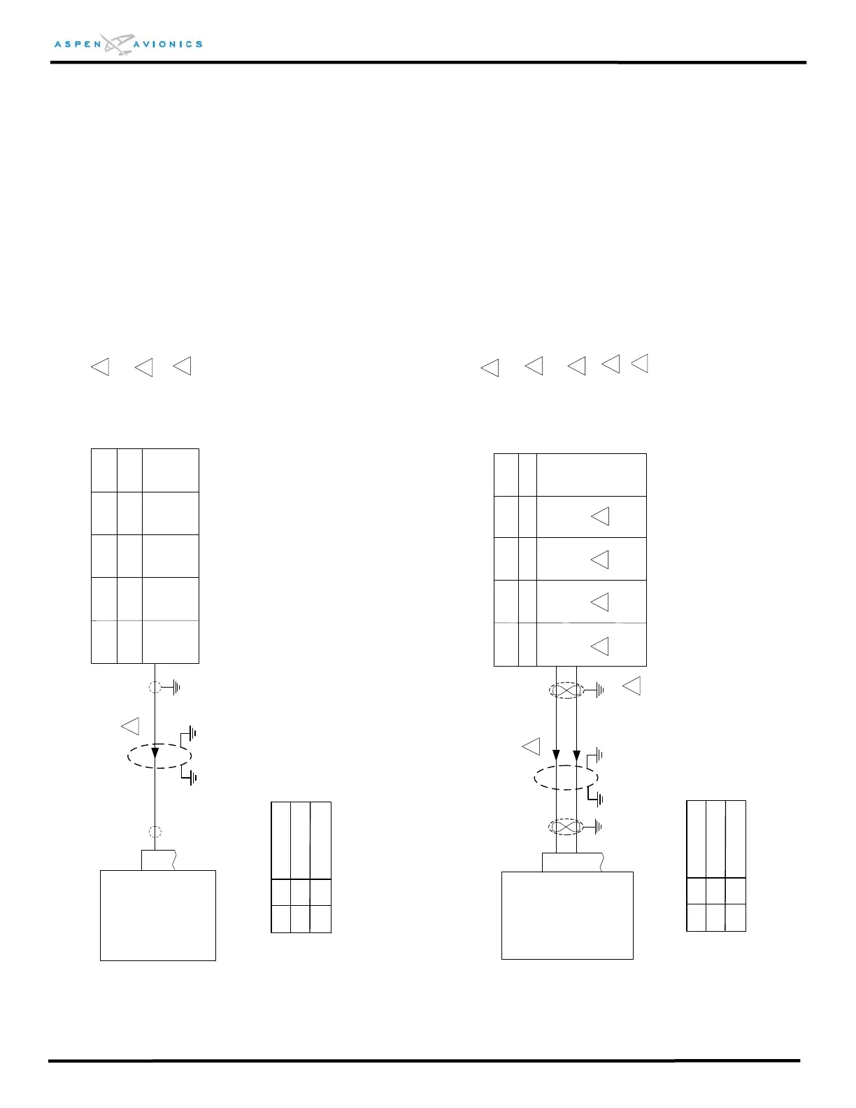
Figure 9.4 Pilot Digital RS-232 Interface
EFD1000
16
429 GPS RX1A
P4001 P5001 P1
46 46 16
429 GPS RX1B
17
47
47
15
Figure 9.5 Pilot Digital ARINC 429 Interface
Configure Garmin ARINC 429 port for
“Low GAMA 429 Graphics w/Int”
GNS400 GNS500
GNC300
GX50/60 GX55
KLN89/B
KLN94
KLN90/A/
B
KLN900
P1
6
GPS150
155/165
P1
15
16
1
1
2
1
Apollo
2001
P1
41
40
ID#1 Description
C
NONE
ID#2
GPS1, No GPS2
No GPS1, No GPS2
2
1
Configure RS-232 output to “Aviation” format
on GPS.
NONE
NONE
ID#1 Description
F
NONE
ID#2
GPS1, No GPS2
No GPS1, No GPS2
NONE
NONE
Over shield or over braid required on this wire
bundle to comply with HIRF & Lightning. Extend
within back shell if possible. Ground at both ends.
2
2
2
Over shield or over braid required on this wire
bundle to comply with HIRF & Lightning. Extend
within back shell if possible. Ground at both ends.
3
3
Configuration Matrix
(see Section 10)
Configuration Matrix
(see Section 10)
4
Back-up NAV indicator maybe required for IFR
use. Consult manufacturers’ installation manual.
3
Configure GPS for “King EFS 40/50”
5
4
Refer to manufacturers’ documentation to verify
the integration data and for information
regarding checkout procedures. This drawing,
as it pertains to the non-Aspen equipment, is for
reference only.
Refer to manufacturers’ documentation to verify
the integration data and for information
regarding checkout procedures. This drawing,
as it pertains to the non-Aspen equipment, is for
reference only.
 Loading...


