EFD1000 Installation Manual
DOCUMENT # A-01-126-00 PAGE 95-225 Revision H
© Copyright 2009 Aspen Avionics Inc.
Over Braid or
Double Shield
Over Braid or
Double Shield
EFD1000
16
429 GPS RX1A
P4001 P4006 P5006P5001
46 46
24
429 GPS RX1B
17
47
24
47
23
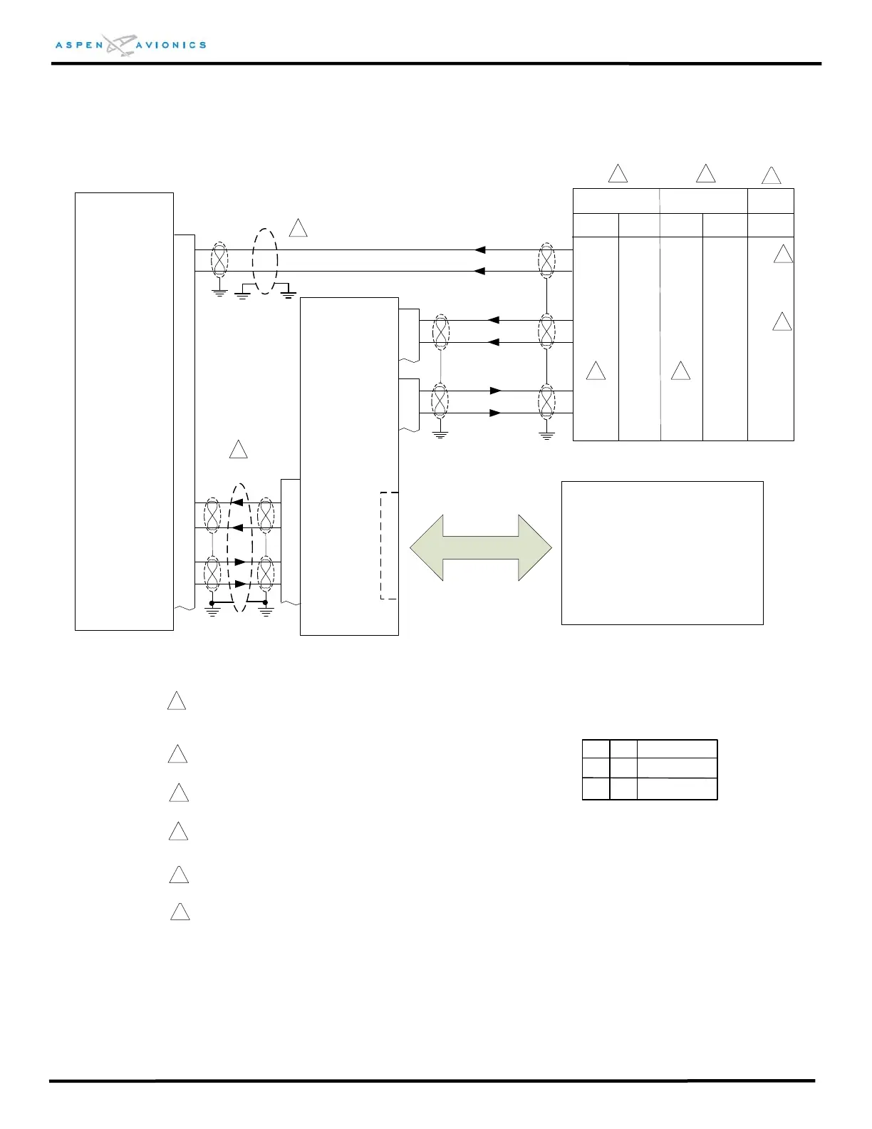
Figure 9.7 Pro Single Digital w/ Autopilot Interface
GNS430(W)(AW) GNS530(W)(AW)
23
1
2
P1
P3
4
5
48(50)
49(51)
48(50)
49(51)
ACU
P3
18
19
26
27 14
1
15
2
VLOC/ACU RX2A
VLOC/ACU RX2B
PFD 429 TX1A
PFD 429 TX1B
Autopilot
See Figure:
9.16 for Bendix King
9.17 for S-TEC
9.18 for Century
9.19 for Cessna ARC
9.20 – 9.23A Flight Director
_
_
_
_
_
_
_
_
_
_
_
_
429 RX1B
429 RX1A
429 TX1B
429 TX1A
A
U
T
O
P
I
L
O
T
429 RX2A
429 TX2A
429 TX2B
429 RX2B
1
ID#1
Description
B
ID#2
NONE
GNS430, No GPS2
With Autopilot
2
GNAV
Use pins 48 & 49 or 50 & 51 not both.
3
1
*GNS530 uses same config as GNS430
1
Over shield or over braid required on this wire
bundle to comply with HIRF & Lightning. Extend
within back shell if possible. Ground at both ends.
4
2
3 3
Configuration Matrix
(see Section 10)
CNX-80
GNS-480
P5
4
24
5
25
8
28
2
R
NONE
GNS480, No GPS2
With Autopilot
6
Pins 4 & 24 may be swapped with pins 5 & 25 if
configured accordingly below.
See Figure 9.27 for GNS-480 configuration.
5
4
4
5
See Figure 9.27 for GNS-430/530 configuration.
Refer to manufacturers’ documentation to verify the
integration data and for information regarding
checkout procedures. This drawing, as it pertains
to the non-Aspen equipment, is for reference only.
This drawing is used for a single GNAV and autopilot interface only.
Use Figure 9.8 if adding a second GPS or Analog Nav2 receiver.
 Loading...


