Ch. 19. Air Temperature Controller Sec. 19.4. Operation
5.
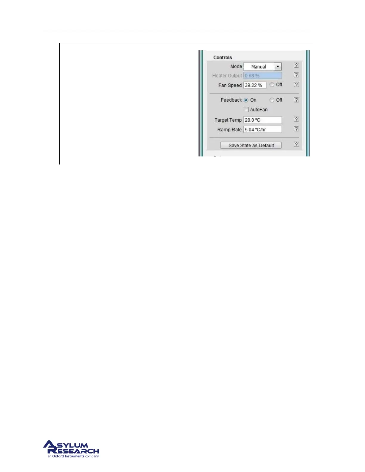
Turn the feedback on:
• Click the feedback control to ON.
• Over the next hours observe the heater
power variation and the head
temperature converging on the
temperature setpoint.
• A properly operating system will apply
between 5% and 15% heater power to
keep the head temperature within 0.1C
of the setpoint.
19.4.2. Further Description of ATC Controls
Heater Output This controls the amount of power provided to the heating coils. The power can be
adjusted to 50% power. Typically the amount of power required to maintain temperature stability is
under 5%. Although not recommended, you can use this control to briefly send a burst of hot air into
the enclosure to accelerate initial warm up time.
Fan Speed Has a range of 0% to 100% and is variable from 39-100%. In cases where you are scanning
near atomically flat surfaces, you may see periodic noise from the fans. Reducing the fan speed will
eliminate this but be aware that you need to circulate air through the Cypher in order to maintain thermal
stability. In most cases, reducing the speed to 39% for a few hours will not be a problem as long as the
lab temperature is sufficiently below the Target Temperature. Noise levels from the fans at 39% show
negligible to no effect on the Cypher’s performance.
Feedback On/Off. Enables the feedback loop which controls the heater power to maintain a constant
head sensor temperature.
Target Temp. The final temperature to be maintained by the feedback loop.
Ramp Rate Rate at which the ATC adjusts the current Setpoint Temperature to achieve the Target Temp.
Note The Setpoint Temperature is located the Temperatures display area. This is a transition tempera-
ture based on the ramp rate parameter changing the feedback loop’s current operating point to the Target
Temp
19.4.3. Explanation of Temperature Sensors
There are three temperature sensors located inside the ATC that are primarily used to monitor the oper-
ating temperature of the unit while it’s being used.
ATC Case This sensor is attached to the inside wall of the ATC box. It is used to monitor the incoming
air from the room which is essentially the room temperature.
BETA
Page 213