Ch. 6. Fluid Imaging in a Droplet Sec. 6.4. Imaging with the Droplet Holder
4.
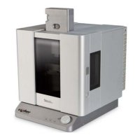
Set the drive frequency and calibrate the
phase signal
• Move the mouse cursor to the apex of
the amplitude peak, right click and
select ’Set Drive Frequency’
• The software will center the pot on the
peak.
• Click on the ’Center Phase’ button in
the tune panel to adjust the phase signal
to the center of it’s range.
5. Click on the ’Stop’ button in the tune panel when the system is tuned.
6.4.2. Imaging Specifics
6.4.2.1. Engaging in fluid in AC mode
As the tip is being lowered to the surface during the engage routine, the Cypher is doing a series of
triggered force curves looking for the free amplitude to equal the setpoint voltage. Once the free am-
plitude is seen as equal to the setpoint voltage, the system stops the approach and is considered to have
found the surface. This works pretty well but in fluid there are several things that can trigger a false
engagement.
• The Feedback Filter - The default frequency response of the feedback filter is 5KHz. Since the
resonance of the cantilever in this example is around 6.5KHz, the instrument is allowed to see
frequencies too close to the oscillating frequency of the lever. This will cause the software to
detect the alternating movement of the cantilever as the amplitude is changing and trigger a false
engagement. Lowering the feedback filter value to around 2KHz will avoid this. Using stiffer
cantilevers with a higher natural resonance will not need this adjustment.
• Hydrodynamic drag - The abrupt drop in the cantilever holder pillar during a motor step can
cause a jump in the deflection signal. This is caused by the drag of the liquid bending a low
spring constant cantilever. Lowering the Feedback Filter to around 2KHz will help reduce this
effect. Stiffer cantilevers will not show this problem.
• The amplitude changes due to the peak shifting frequency - As the probe is lowered to the surface,
the amount of liquid between the glass in the droplet holder and the sample surface can change
the coupling of the drive signal into the cantilever. This may excite the cantilever at a different
frequency so a previously tuned cantilever may not be in tune anymore. If the instrument trig-
gers an engagement, you may want to go back to the tune panel and do a single tune to see the
amplitude response and re-tune if necessary.
Check for a real tip engage by clicking on the ’Engage’ button in the Sum and Deflection meter panel.
Reduce the setpoint voltage in the master controls panel and watch the behavior of the Z control voltage.
If by lowering the setpoint voltage you see the Z voltage move all the way to 150volts then the system
BETA
Page 67