Ch. 7. iDrive Imaging Sec. 7.1. Nomenclature
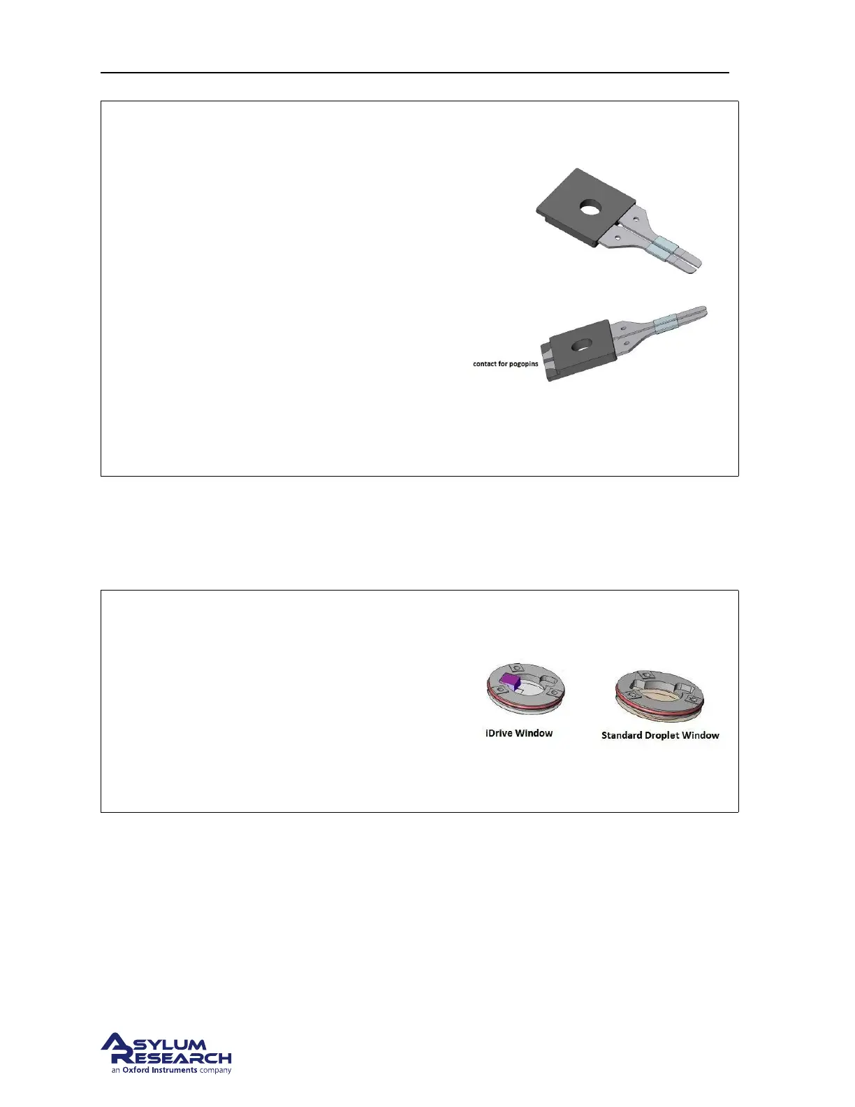
Figure: Here are top and bottom views of the
split clip assembly.
Notice:
• the exposed area of the clips which are the
contacts for the pogo pins.
• the step along the molded section is used
for keying the clip into the droplet holder
body.
• the bands of Teflon act as a hydrophobic
barrier.
• like the standard droplet holder clip, the
bottom of the clips are tapered to provide
sample clearance.
7.1.1.2. The window assembly
The window assembly used in the iDrive droplet holder differs only in that there is a magnet bonded to
the top side of the glass window just above the cantilever.
Figure Here is a view of both window
assemblies for comparison.
Note Due to limited space in the design of the
droplet holders, the windows are not intended to
be interchangeable. However, the standard
window will fit into the body of the iDrive holder
but the window from the iDrive holder will not fit
in the standard droplet holder body.
7.1.1.3. Installing an iDrive cantilever
Installing an iDrive style cantilever is basically the same process as a standard cantilever. The difference
is that you need to pay close attention to the placement of the cantilever chip so that the split in the
contact area on the chip is between the split in the cantilever clip. This will create a circuit so that AC
current flows up through one clip, through the cantilever and returns through the other clip.
BETA
Page 77