Ch. 7. iDrive Imaging Sec. 7.1. Nomenclature
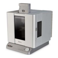
Figure Here is a view of the surface of an iDrive
style cantilever.
Note
• The entire surface of the cantilever is
coated with a layer of gold.
• The insulating lines are etched in surface
to create to contact pads.
• Each of the outer pads are connected to
one leg of the smaller cantilever.
• The center area is isolated and is not
associated with the cantilever’s function.
• The typical resistance between the
electrodes is 10 Ohms with both of the
small cantilevers intact.
• It is okay to scan with both levers intact.
Breaking off the unused small lever will
simply raise the resistance of the
conducting path but generally doesn’t
improve performance.
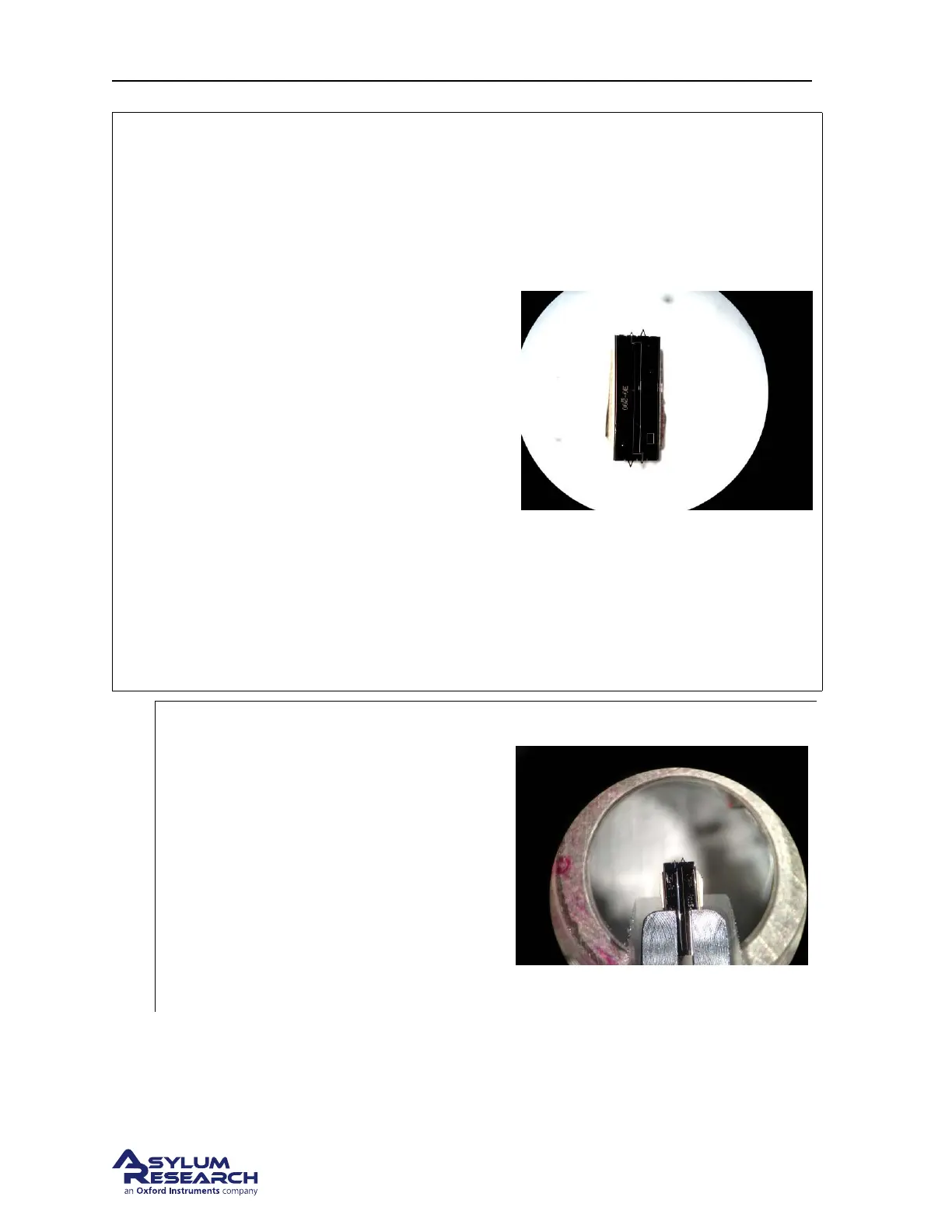
1.
Install an iDrive cantilever into the droplet
holder
• Align the chip under the electrodes so
that only one cantilever clip contacts
one of the contact pads.
• Use an Ohm meter to check the
resistance between the cantilever holder
spring clips.
Note The center narrower electrode is
isolated so it’s okay to allow one of the clips
to touch it.
7.1.2. Preparing for Imaging
Since this cantilever holder is nearly identical mechanically to the Droplet Cantilever Holder, please
refer to
Chapter 7 on page 75 for details on
BETA
Page 78