Chapter 5 - Accessories
UM-22100H-U User manual ATEQ D520 Page 109/122
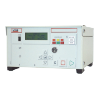
2.7.4. Indicators
The L.E.D. tricolour indicators situated near the F1 to F4 keys allow the display of the
state of the cycle requested:
¾ green, cycle ok,
¾ red, cycle bad,
¾ orange cycle in progress.
2.7.5. Fixed function keys
The four other push to make buttons (situated on the right hand side) are the push
buttons possessing the following functions:
¾ selection of the rise program (white),
¾ selection of the drop program (black),
¾ cycle start button (green),
¾ cycle stop/reset button (red).
Reminder: these buttons functions are fixed and cannot be modified.
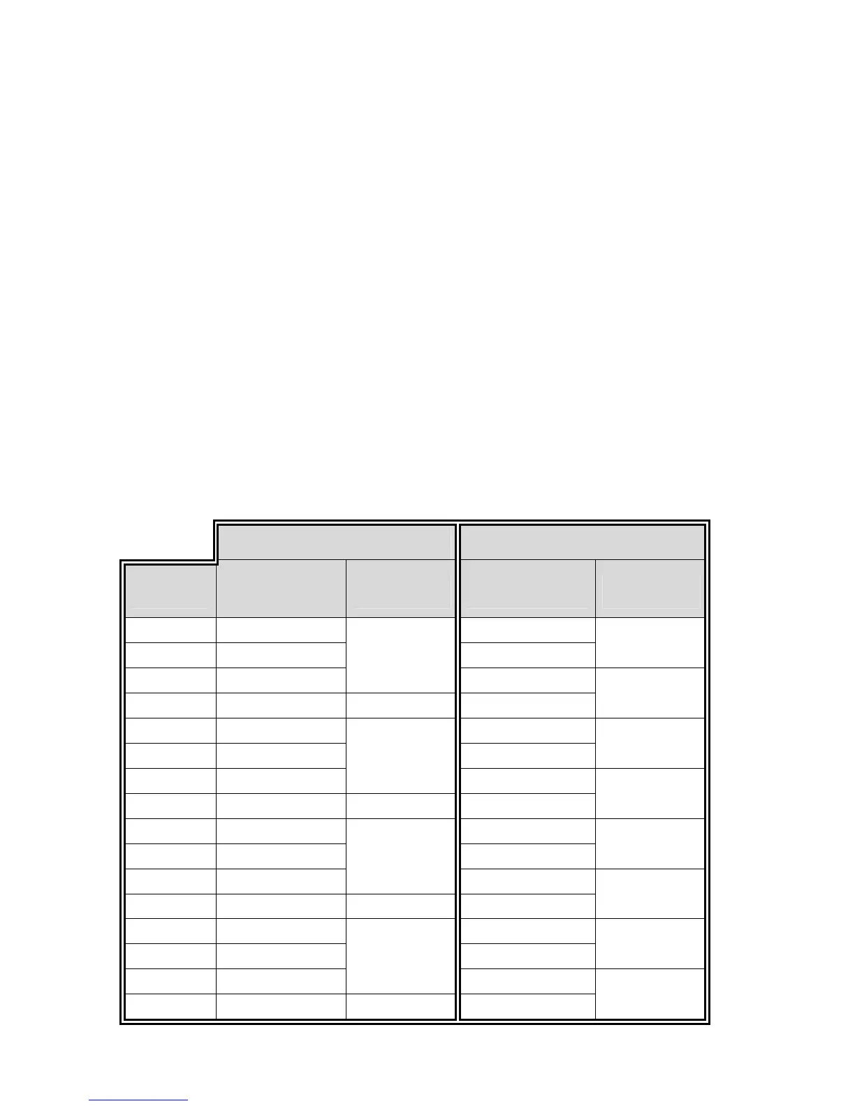
2.7.6. Installation of the remote control on the RC5
J2 connector (outputs) J3 Connector (inputs)
Pins
24 V 10 mA
Outputs
L.E.D. Inputs Functions
1
Green anode Input 1
2
Cathode (0 V) 24 V
F1
3
Red anode
F1
Input 2
4
0 V 24 V
F2
5
Green anode Input 3
6
Cathode (0 V) 24 V
F3
7
Red anode
F2
Input 4
8
0 V 24 V
F4
9
Green anode Input 5
10
Cathode (0 V) 24 V
RISE
11
Red anode
F3
Input 6
12
0 V 24 V
DROP
13
Green anode Input 7
14
Cathode (0 V) 24 V
RESET
15
Red anode
F4
Input 8
16
0 V 24 V
START