§
Remove the mains power supply cord from the power cord
connector.
§
Locate the slot in the module cover door hinge. The hinge is a the
left side of the cover door, and the slot in the hinge is visible in the
power cord connector cavity. Insert a small screwdriver or similar tool
in the slot and pry the cover door hinge outward. The cover door will
snap out, and then can be pivoted on its hinge for access to the fuse
block assembly and voltage selector card.
Changing the Mains Supply Voltage Configuration
§
Open the Power Entry Module as described above.
§
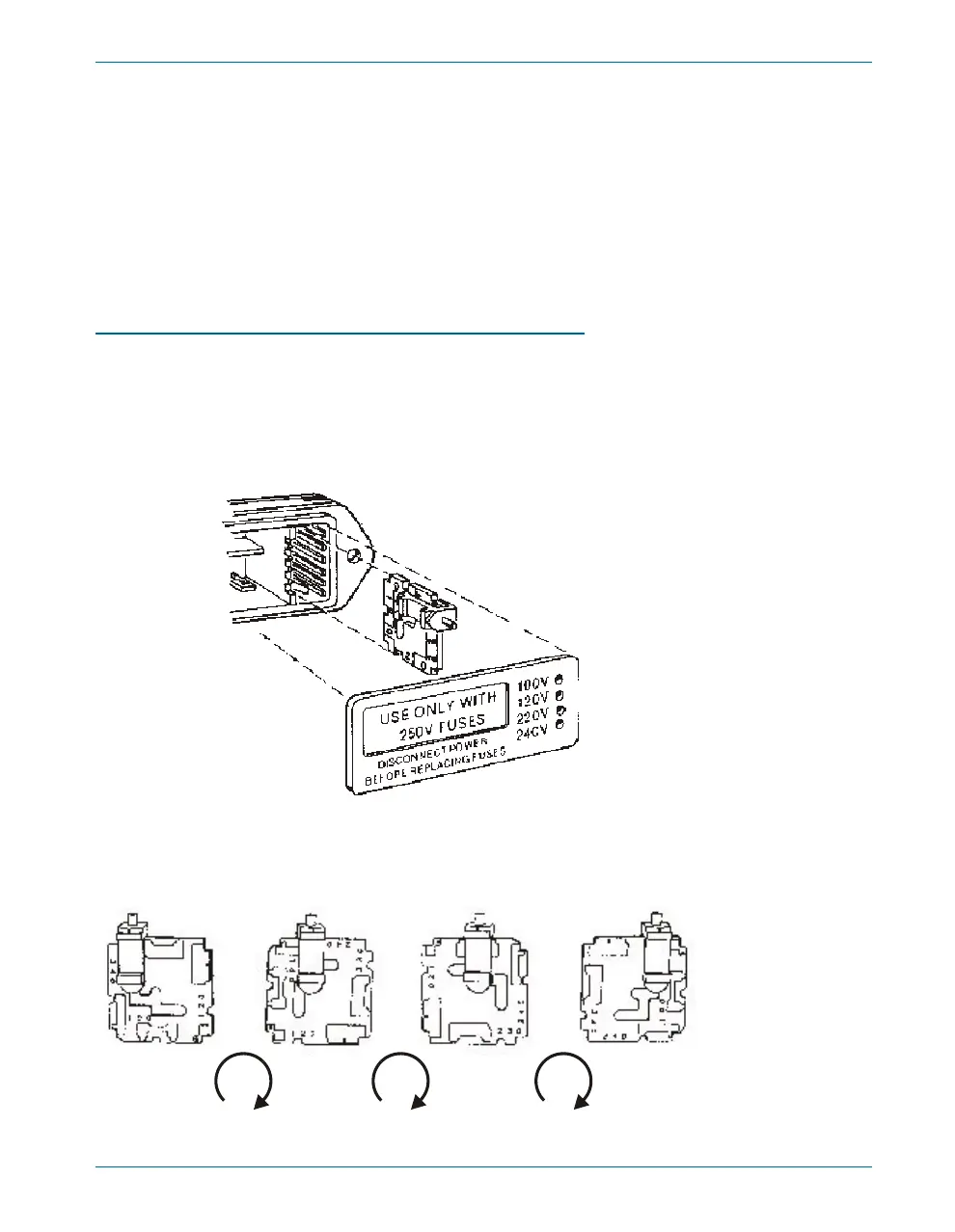
The voltage selector card is a small circuit board fitted with a white
plastic indicator pin, installed in a housing on the right side of the
Power Entry Module as shown in Figure 4. Pull the voltage selector
card straight out of the housing, using narrow pliers to grab the card.
Do not use the indicator pin as a handle.
§
Orient the selector card so that the desired input voltage is readable
at the bottom, shown in Figure 5. Then move the indicator pin to
Setting Up the ATS-2 Hardware Chapter 2: Installation and Setup for APIB
Getting Started with ATS-2 11
Figure 4. Changing the mains power supply voltage.
100V 120V 230V 240V
90° 90° 90°
Figure 5. Voltage selector card positions.