the out puts, click the OUTPUTS “OFF” but ton near the cen ter of the
panel. The but ton will turn green, and you will hear re lays click in the
ATS-2 hard ware. The peak me ters in the an a log in put panel will show ap -
prox i mately 1.414 Vpp. The peak me ters in di cate the pres ence of signal at
the analog inputs.
The ste reo gen er a tor out puts can be in di vid u ally dis abled with the
‘CHA’ and ‘CHB’ but tons next to the ‘OUTPUTS’ field. Click on the ‘CHB’
but ton. The but ton will turn gray, re lays will click in the hard ware, and the
Chan nel B peak me ter on the an a log in put panel will in di cate a level close
to zero.
Analyzer Panel
The de fault An a lyzer panel is a real-time au dio an a lyzer. It pro vides
con tin u ous read ings of sig nal level and fre quency. It also al lows you to fil -
ter the au dio sig nal and mea sure pa ram e ters such as to tal har monic dis tor -
tion, phase, and so on. It is a ste reo in stru ment, with the me ters on the left
of the panel re port ing chan nel A read ings, and those on the right reporting
channel B readings.
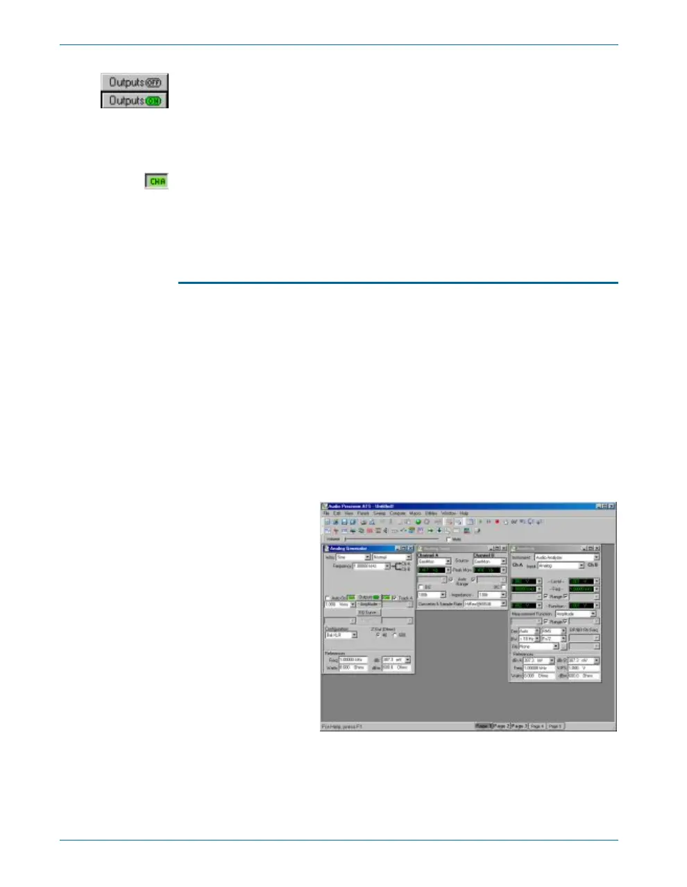
At this point, you should have the setup shown in Fig ure 15:
§
Analog generator channel A producing a 1 V, 1 kHz sine wave.
§
Analog generator channel B disabled.
§
Analog inputs A and B set to the internal generator path (GenMon).
The top most me ters in the de fault An a lyzer panel show the au dio level
in V rms. You should see ap prox i mately 1 V in the left-hand me ter (chan -
nel A), and ap prox i mately 0 V in the right-hand me ter (chan nel B). Click
the ‘CHB’ but ton on the An a log Gen er a tor panel to re-en able the chan nel
Chapter 5: Quick Guides Quick Guide to the Analog Signal Path
32 Getting Started with ATS-2
Figure 15. Current
workspace.