§
DIGITAL OUTPUTS
In single-connector mode, ATS-2 transmits stereo digital audio
simultaneously on the XLR “I” connector, the BNC connector, and
the optical connector. In dual-connector mode, channels A and B are
transmitted on the XLR “I” and “II” connectors, respectively.
§
DIGITAL INPUTS
In single-connector mode, ATS-2 receives stereo digital audio from
the XLR “I” connector, the BNC connector, or the optical connector.
In dual-connector mode, channels A and B are received on the XLR
“I” and “II” connectors, respectively.
§
ANALOG OUTPUTS
The ATS-2 analog generator outputs (both “A” and “B” channels) are
available as unbalanced signals on the BNC connectors and as
balanced signals on the XLR connectors.
§
ANALOG INPUTS
The XLR balanced and the BNC unbalanced connectors (both “A”
and “B” channels) are connected to the ATS-2 analyzer inputs.
See Chap ter 4 of the ATS-2 User’s Man ual for more in for ma tion about
the ATS-2 in puts and out puts and the pan els as so ci ated with them.
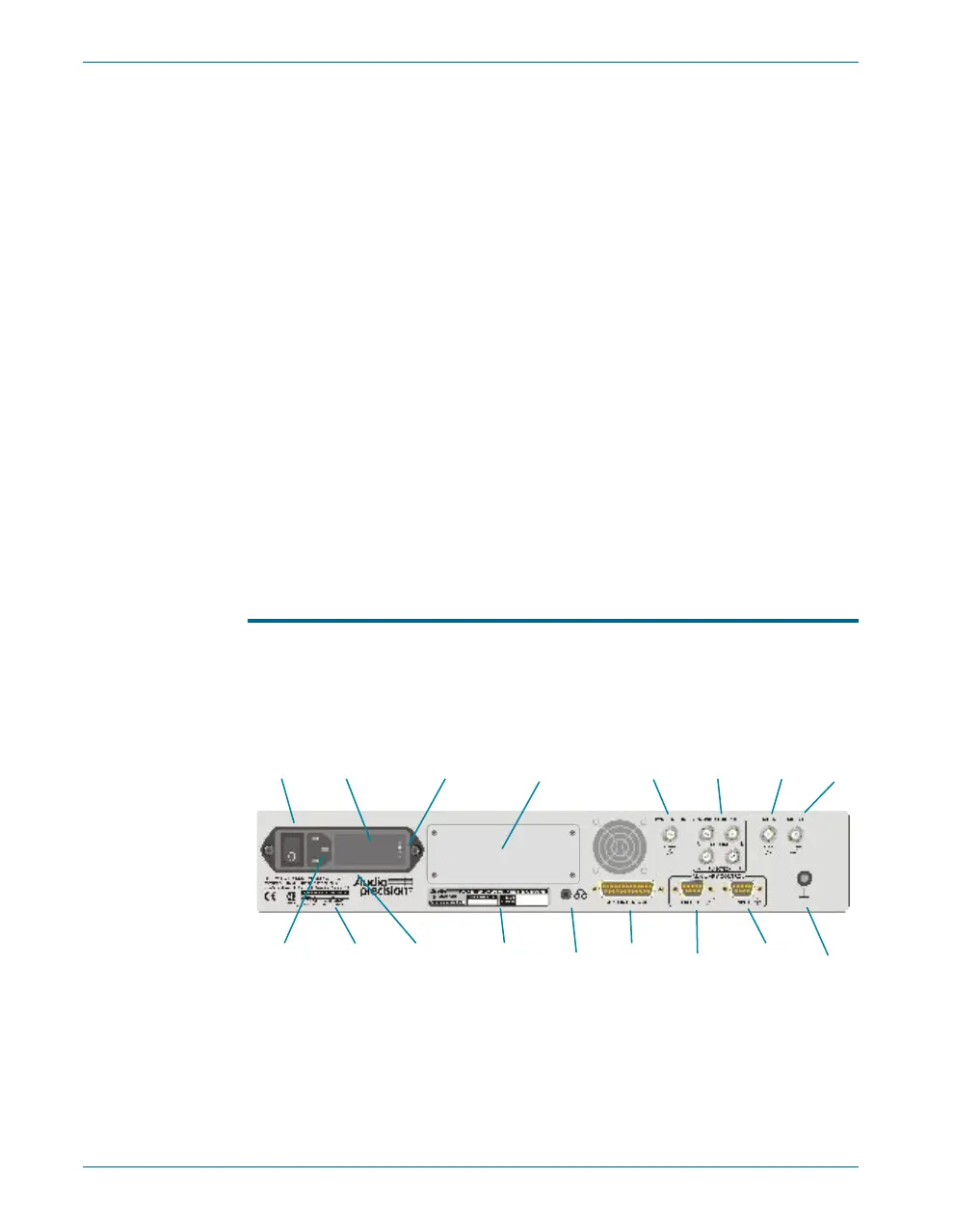
ATS-2 Rear Panel
The ATS-2 in ter face, mon i tor, head phone, trig ger, sync, and util ity con -
nec tions are mounted on the rear panel.
§
POWER ENTRY MODULE—this module includes:
Ÿ POWER SWITCH—This switch turns the mains power supply to
the ATS-2 hardware ON ( I ) or OFF ( O ).
Chapter 3: Hardware Overview ATS-2 Rear Panel
18 Getting Started with ATS-2
Headphone
Jack
APIB
Auxiliary
Control Out
Auxiliary
Control In
Ground
Connector
S/N, Option
Label
Fuse
Replacement
Information
Power
Cord
Connector
Power
Entry
Module
Power
Switch
Mains Voltage
Indicator
Reserved for
GPIB Panel
Fuse Holder /
Mains Supply
Voltage Jumper
Sync / Ref In
Monitor
Outputs
Trig In Trig Out
Figure 12. ATS-2 rear panel, APIB-only configuration.