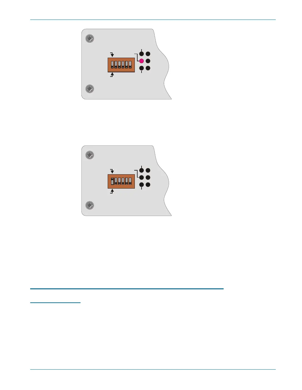
To use APIB to con trol ATS-2, se lect APIB on the rear-panel switch as
shown in Fig ure 26 (left-most switch clicked up to “1”), and con nect a ca -
ble from the APIB in ter face card on the con trol ling com puter to the port
on ATS-2.
Whether con trolled by APIB or GPIB, ATS-2 still uses APIB to con trol
other Au dio Pre ci sion APIB in stru ments and ac ces so ries such as the
DCX-127 and the SWR-2122 fam ily of switch ers. Fig ure 27 il lus trates how
to con nect these de vices to the ATS-2 when the GPIB port is the con trol
port; Fig ure 28 il lus trates how to con nect an APIB con trol ler to this sys tem
when the GPIB port is disabled.
Establishing GPIB Communication
GPIB Connection
The ATS-2 with Op tion GPIB in stalled has a 24-pin GPIB-com pat i ble
con nec tor on the rear panel. This D-shell con nec tor con forms to the me -
chan i cal re quire ments of IEEE-488.1-1987. The in stru ment is con nected to
the in stru ment con trol ler via an ap pro pri ate ca ble. The in stru ment con trol -
ler (a com puter) must have a cor re spond ing GPIB in ter face port. Stan dard
GPIB ca bles are de signed so they can be stacked if needed to con nect
mul ti ple instruments into your GPIB system.
The GPIB Software Development Process Chapter 7: GPIB Configuration
Getting Started with ATS-2 63
ERR
MAV
LA
TA
SRQ
GPIB
GPIB
4
0
1
2 18 16
APIB
ADDRESS
Figure 25. The ATS-2 Option GPIB panel; detail, shown in GPIB mode.
ERR
MAV
LA
TA
SRQ
GPIB
GPIB
4
0
1
2 18 16
APIB
ADDRESS
Figure 26. The ATS-2 Option GPIB panel; detail, shown in APIB mode.