point UP, opposite the indicated voltage. Seat the pin assembly in the
notch on the board edge.
§
Insert the voltage selector card into the housing with the printed side
of the card facing toward the mains power connector. The card edge
indicating the desired voltage should enter the housing first.
§
Confirm that the correct fuse or fuse combination is installed for the
intended input voltage (refer to the fuse ratings marked on the
instrument rear panel). If necessary, change the fuse type as
described in the following section.
§
Close the module the cover door and verify that the indicator pin
shows the desired voltage.
Once you have ver i fied that the line volt age se lec tion is cor rect, con nect
the power cord from a mains power out let to the power cord con nec tor on
the in stru ment rear panel.
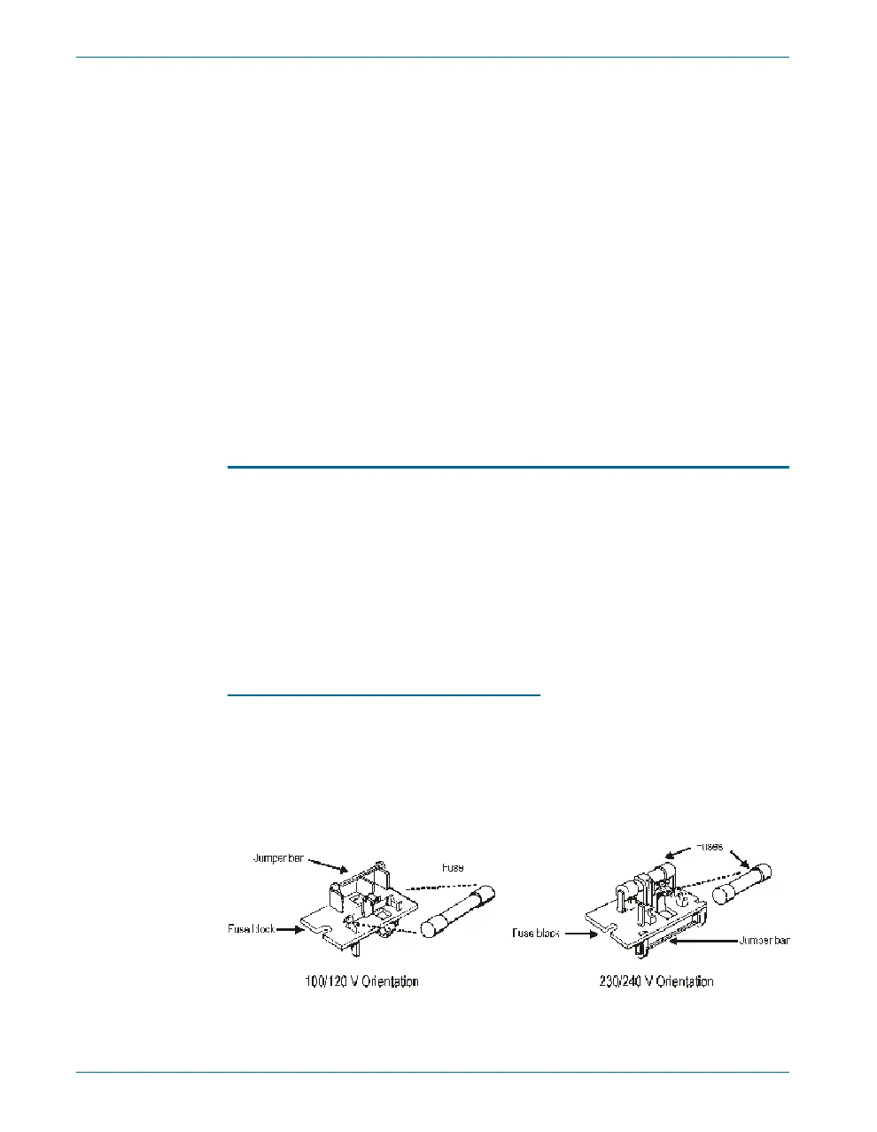
Fuse Information
The power en try mod ule ac com mo dates two fus ing ar range ments, as il -
lus trated in Figure .
§
The North American fusing arrangement uses a single type 3AG
(0.25" ´ 1.25") SB (slow blow) fuse.
§
The European fusing arrangement uses two 5´20 mm IEC-approved
type T fuses.
Re fer to the la bel on the rear panel for fuse cur rent rat ings.
Changing the Fusing Arrangement
To re place a fuse or change the fus ing ar range ment, pro ceed as fol lows:
§
Remove the mains power cord from the power cord connector and
open the Power Entry Module as described above.
§
Using narrow pliers, pull the fuse assembly out of the housing.
Chapter 2: Installation and Setup for APIB Setting Up the ATS-2 Hardware
12 Getting Started with ATS-2
Figure 6. Fuse Block Orientation for North American (100/120 V)
and European (230/240 V) operation..