in stru ment. Le gal ad dresses are 0 through 30. Set each switch up for a bi -
nary 1 or down for a binary 0.
The left-most switch in the bank sets the con trol mode, in de pend ent of
the GPIB ad dress switch set tings. Click the switch to 0 (down) to set the
con trol mode to GPIB.
The APIB port must not be connected to an active Audio
Precision APIB interface card when the GPIB mode is
selected.
Set the switch to 1 (up) to set the con trol mode to APIB. The APIB
mode dis ables the GPIB in ter face (the pins are all set to the high-im ped -
ance state) and en ables APIB to con trol the ATS-2.
Chapter 7: GPIB Configuration The GPIB Software Development Process
66 Getting Started with ATS-2
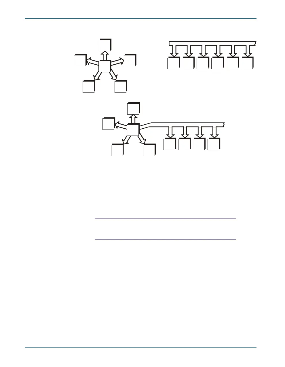
STAR CONFIGURATION
COMBINATION STAR AND
LINEAR CONFIGURATION
LINEAR CONFIGURATION
B
C
A
C
B
D
F
D
E
E
F
B
G
C
H
D
I
E
A F
A
Figure 29. GPIB devices may be connected in star, linear,
or combination star/linear configurations.