Version 5.2 35 September 2007
SIP User's Manual 3. Installation
3.1.4.1 Grounding the Mediant 2000
Permanently connect the device to a suitable earth with the protective earthing screw on
the rear connector panel, using 14-16 AWG wire.
Electrical Earthing
The unit must be permanently connected to earth via the screw provided at the
back on the unit. Use 14-16 AWG wire and a proper ring terminal for the
earthing.
3.1.4.2 Connecting the E1/T1 Trunk Interfaces
Connect the E1/T1 Trunk interfaces using either Telco (for Mediant 2000 with 16 spans) or
RJ-48 (for Mediant 2000 with 1, 2, 4, or 8 spans) connectors:
¾ To connect E1/T1 trunks using 50-pin Telco connectors (16-trunk
device), take these 3 steps:
1. Attach the Trunk cable (of at least 26 AWG UTP) with a 50-pin male Telco connector
to the 50-pin female Telco connector labeled Trunks 18 on the Mediant 2000 Rear
Transition Module (RTM).
2. Connect the other end of the Trunk cable to the PBX/PSTN switch.
3. Repeat steps 1 and 2 for the other Trunk cable, but this time connect it to the
connector labeled Trunks 916.
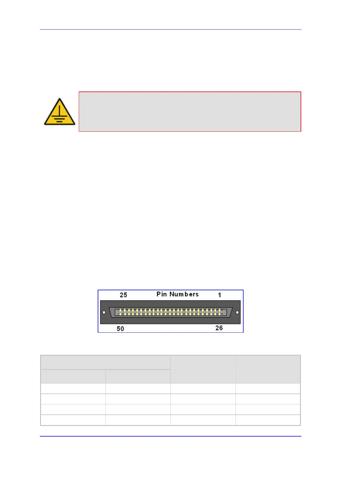
The 50-pin male Telco cable connector must be wired according to the pinout in the table
below, and to mate with the female connector illustrated in the figure below.
Figure 3-5: 50-pin Female Telco Board-Mounted Connector
Table 3-3: E1/T1 Connections on each 50-pin Telco Connector
E1/T1 Trunk Number
1 to 8 9 to 16
Tx Pins (Tip/Ring) Rx Pins (Tip/Ring)
1 9 27/2 26/1
2 10 29/4 28/3
3 11 31/6 30/5
4 12 33/8 32/7