Version 5.2 9 September 2007
SIP User's Manual Contents
List of Figures
Figure 1-1: Mediant 2000 Typical Application ........................................................................................16
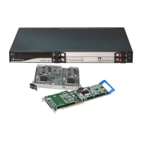
Figure 2-1: Mediant 2000 Front Panel....................................................................................................19
Figure 2-2: Front View of TP-1610 cPCI Blade......................................................................................21
Figure 2-3: RTM-1610 Rear Panel with two 50-pin Connectors for 16 Trunks ......................................24
Figure 2-4: RTM-1610 with 8 RJ-48c Connectors for 8 Trunks .............................................................24
Figure 2-5: TP-260 Board Description....................................................................................................25
Figure 2-6: RJ-45 Connector Pinouts.....................................................................................................27
Figure 2-7: RJ-48c Connector Pinouts ...................................................................................................27
Figure 3-1: 19-inch Rack and Desktop Accessories ..............................................................................30
Figure 3-2: Front View with 19-inch Rack-Mount Brackets ....................................................................32
Figure 3-3: Rear-Panel Cabling (e.g., 16 Trunks, Dual AC Power) .......................................................33
Figure 3-4: Rear-Panel Cabling (8 Trunks, DC Power)..........................................................................34
Figure 3-5: 50-pin Female Telco Board-Mounted Connector.................................................................35
Figure 3-6: RJ-48c Connector Pinouts ...................................................................................................36
Figure 3-7: RJ-45 Connector Pinouts.....................................................................................................37
Figure 3-8: RS-232 Connector Pinouts ..................................................................................................37
Figure 3-9: DC Power Terminal Block Screw Connector .......................................................................39
Figure 3-10: DC Power Terminal Block Crimp Connector .....................................................................39
Figure 3-11: RJ-48c Connector Pinouts .................................................................................................45
Figure 3-12: E1/T1 Cable Splitter...........................................................................................................45
Figure 3-13: RJ-45 Connector Pinouts...................................................................................................46
Figure 4-1: Startup Process....................................................................................................................49
Figure 4-2: Quick Setup Screen .............................................................................................................54
Figure 5-1: Enter Network Password Screen.........................................................................................60
Figure 5-2: Searched Result Screen ......................................................................................................63
Figure 5-3: Searched Parameter Highlighted in Screen ........................................................................64
Figure 5-4: Customized Web Interface Title Bar ....................................................................................65
Figure 5-5: Customized Web Interface Title Bar ....................................................................................65
Figure 5-6: Image Download Screen......................................................................................................66
Figure 5-7: User-Defined Web Welcome Message after Login..............................................................70
Figure 5-8: General Parameters (Protocol Definition Submenu) ...........................................................72
Figure 5-9: Proxy & Registration Screen................................................................................................86
Figure 5-10: Coders Screen ...................................................................................................................96
Figure 5-11: DTMF & Dialing Screen .....................................................................................................99
Figure 5-12: Stand-Alone Survivability Screen.................................................................................... 112
Figure 5-13: Source Phone Number Manipulation Table for Tel-to-IP Calls....................................... 114
Figure 5-14: Phone Context Table Screen.......................................................................................... 118
Figure 5-15: Routing Tables - General Parameters Screen................................................................ 120
Figure 5-16: Tel to IP Routing Table Screen....................................................................................... 124
Figure 5-17: IP to Trunk Group Routing Table Screen ....................................................................... 127
Figure 5-18: Internal DNS Table Screen ............................................................................................. 129
Figure 5-19: Internal SRV Table Screen ............................................................................................. 130
Figure 5-20: Reasons for Alternative Routing Screen......................................................................... 131
Figure 5-21: Release Cause Mapping Screen (e.g., ISDN to SIP) ..................................................... 132
Figure 5-22: Coder Group Settings Screen......................................................................................... 133
Figure 5-23: IP Profile Settings Screen ............................................................................................... 137
Figure 5-24: Trunk Group Table Screen ............................................................................................. 138
Figure 5-25: Trunk Group Settings Screen ......................................................................................... 140
Figure 5-26: Digital Gateway Parameters Screen............................................................................... 142
Figure 5-27: RADIUS Parameters Screen .......................................................................................... 148
Figure 5-28: IP Settings Screen .......................................................................................................... 153
Figure 5-29: Application Settings Screen ............................................................................................ 157
Figure 5-30: NFS Settings Screen ...................................................................................................... 160
Figure 5-31: IP Routing Tablre Screen................................................................................................ 162
Figure 5-32: VLAN Settings Screen .................................................................................................... 164