- INSTALLER 7 & 11kW HRC
70
HIGH TEMPERATURE HEAT PUMP
MANUAL -
15
3.2.5 - Desludging
We would advise you to t a settling tank (not supplied) on
under oor heating installations.
• The installation MUST be rinsed and
desludged before making the hydraulic
connection with the heat pump.
3.2.7 - Heating circuit
3.2.7.2 - Back ow prevention device
3.2.6 - Heat Pump water inlet lter (supplied)
A 1’’ valve with a built-in 500μm lter must be tted to the water
inlet piping on the Heat Pump:
• Respect the ow direction of the lter (arrow on the
valve)
• Install the 1’’ valve with lter on the inside of the
building and ensure it is thermally insulated
Clean the lter several times as soon as
the Heat Pump circulator pump has been
activated (take care to switch the circulator pump o
before cleaning).
• Clean the lter at least once a year.
For under oor heating installations, the
piping for the heating circuit must not be
under 1’’ in diametre.
3.2.7.1 - Heating circuit ow rate
• For heating circuits with radiators, fan coil units or under oor
heating:
The ow rate must be su cient to ensure that the di erence in
temperature between the leaving and return points is not over
15K in radiator or fan coil unit circuits or 7K in under oor heating
circuits.
For installations which have thermostatic valves, this test must
be carried out with all valves open.
The heating capacity from the heat radiating sources determines
the heating water ow rate and allows you to check that the
sections, lengths and layout of the hydraulic distribution
network are compatible with the Pilot circulator pump.
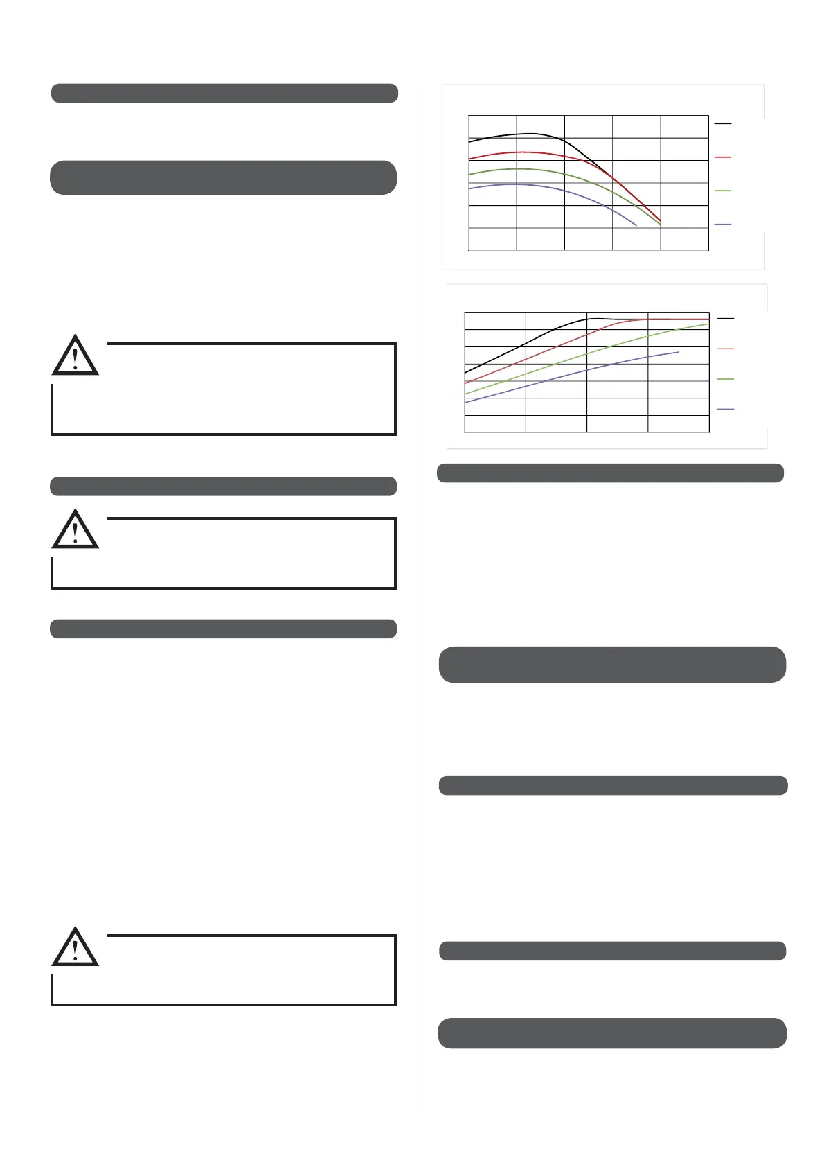
Adjust the speed (I, II, III, IV) of the UPM3 15-70 circulator pump
which is tted to the Pilot to the characteristics of the hydraulic
circuit using the curve chart at top of next column: ow rate Q
(m
3
/h) / pressure head H(mCE).
French law (articles 16.7 and 16.8 of the "Règlement Sanitaire
Départemental") stipulates that a type CB back ow prevention
device must be tted. This device must be at di erent, non-
regulated pressure zones, in accordance with the NF P 43-011
standard. This is also an obligatory requirement in other countries
so it is important to check the current laws and standards in
the country of installation and ensure that your installation is
in compliance with them. The back ow prevention device is
designed to prevent incoming heating water from going into the
drinking water circuit. It must be connected to mains drainage.
3.2.7.4 - Insulating the piping
3.2.7.5 - Expansion vessel
3.2.7.6 - Frost protection and water
treatment
3.2.7.3 - Degassing the heating circuit
All necessary measures must be taken to ensure that the
installation can be continuously degassed. Automatic air valves
should be placed at each high point of the installation and
manual air valves should be tted on each radiator.
Insulants must comply with DTU 67.1 or the current regulations in
the c
ountry of installation.
All visible piping and accessories (circulator pump, expansion
v
essel, valve, etc...) must be insulated
. Remember to insulate the
distribution manif
olds and the return and supply ow pipes to the
under oor heating circuit; remember to insulate
the piping which
c
onnects the Heat Pump to the Pilot.
An expansion vessel needs to be tted onto the heating circuit.
See Appendix 4 for help on sizing.
See appendices A3 et A5.
0,0
1,0
2,0
3,0
4,0
5,0
6,0
0,0 0,5 1,0 1,5 2,0 2,5
H(mCE)
Q(m3/h)
CirculateurUPM31550FLEXAS
hauteurmanométrique
vitesse4
réglage
usine:
vitesse3
vitesse2
vitesse1
UPM3 Flex AS 15-50 GGMBP3 AU CIRCULATOR PUMP
Pressure head
Speed 4
Speed 3
Speed 2
Speed 1
0
5
10
15
20
25
30
35
0,0 0,5 1,0 1,5 2,0
P(W)
Q(m3/h)
CirculateurUPM31550FLEXAS
puissanceabsorbée
vitesse4
réglage
usine:
vitesse3
vitesse2
vitesse1
UPM3 Flex AS 15-50 GGMBP3 AU CIRCULATOR PUMP
Power consumption
Speed 4
Speed 3
Speed 2
Speed 1