- INSTALLER 7 & 11kW HRC
70
HIGH TEMPERATURE HEAT PUMP
MANUAL -
67
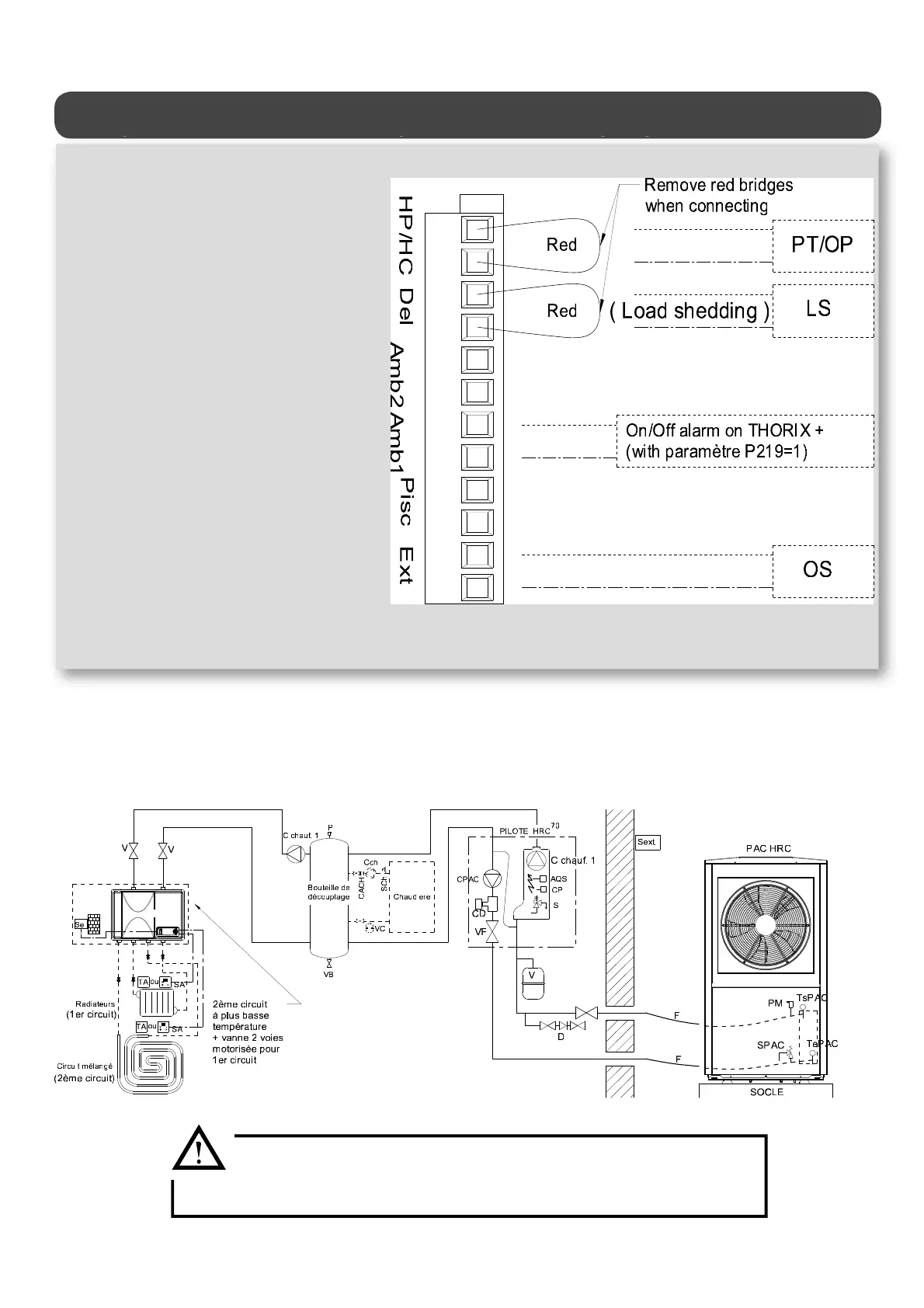
Hydraulic schematic diagram -1 RADIATOR CIRCUIT and 1 MIXED CIRCUIT-
with optional 2
nd
circuit at a lower temperature (Ref.751014) -pool possible- + boiler
HPCP = circulator pump for Heat Pump circuit
C1CP = circulator pump for heating circuit 1
FRM = Heat Pump circuit ow rate monitor
SV = 3-bar safety valve
A = air valve
SP = HRC
70
Pilot temperature sensor (or outgoing water
sensor OW)
AQS = 110°C safety aquastat with manual reset
WP = water pressure sensor
SRV = sludge removal valve
FV = lter valve for Heat Pump circuit
V = stop valves
EV = expansion vessel
BPD = back ow prevention device
F = exible hose for Heat Pump connection
MAV = manual air valve
HPSV = Heat Pump safety valve, set to 2.5 bar
HPIWS = Heat Pump incoming water temperature sensor
HPOWS = Heat Pump outgoing water temperature sensor
EBCP = existing boiler circulator pump
EVE = expansion vessel for existing installation
BSV = safety valve for existing boiler
OS = HRC
70
Pilot Heat Pump outdoor temperature sensor
UTL 1 = Temperature-limiting safety device if circuit 1 is
under oor heating
UTL2 = temperature limiting safety device for the heat pump
circulator pump if circuit 1 is an under oor heating
circuit
FRM SP = swimming pool circuit ow rate monitor
S pool = pool sensor (optional, included in swimming pool kit)
C pool = circulator pump for pool circuit
3WV = 3-way valve for radiator circuit (winter) or pool circuit
(summer)
BCV = boiler check valve
RT or RTS = room thermostat or room temperature sensor on 2
nd
circuit at a lower
temperature ‘‘Thorix Evolution’’.
UTL = Temperature limiting safety device on 2nd, lower-temperature circuit
‘‘Thorix Evolution’’
On the Pilot: • It is mandatory to activate the rst circuit (RADIATOR C-1) .
• Activate the room thermostat input (THERMOSTAT A-1) on the 1
st
circuit in order to monitor Heat Pump operation using the
on/o alert output on the Thorix Evolution (set P219 = 1 on the Thorix Evolution)
The two under oor temperature limiters (UTL1 & UTL2) MUST be
connected to terminals 1-2 and 4-5 (see § «Under oor heating circuit
application»)