- INSTALLER 7 & 11kW HRC
70
HIGH TEMPERATURE HEAT PUMP
MANUAL -
63
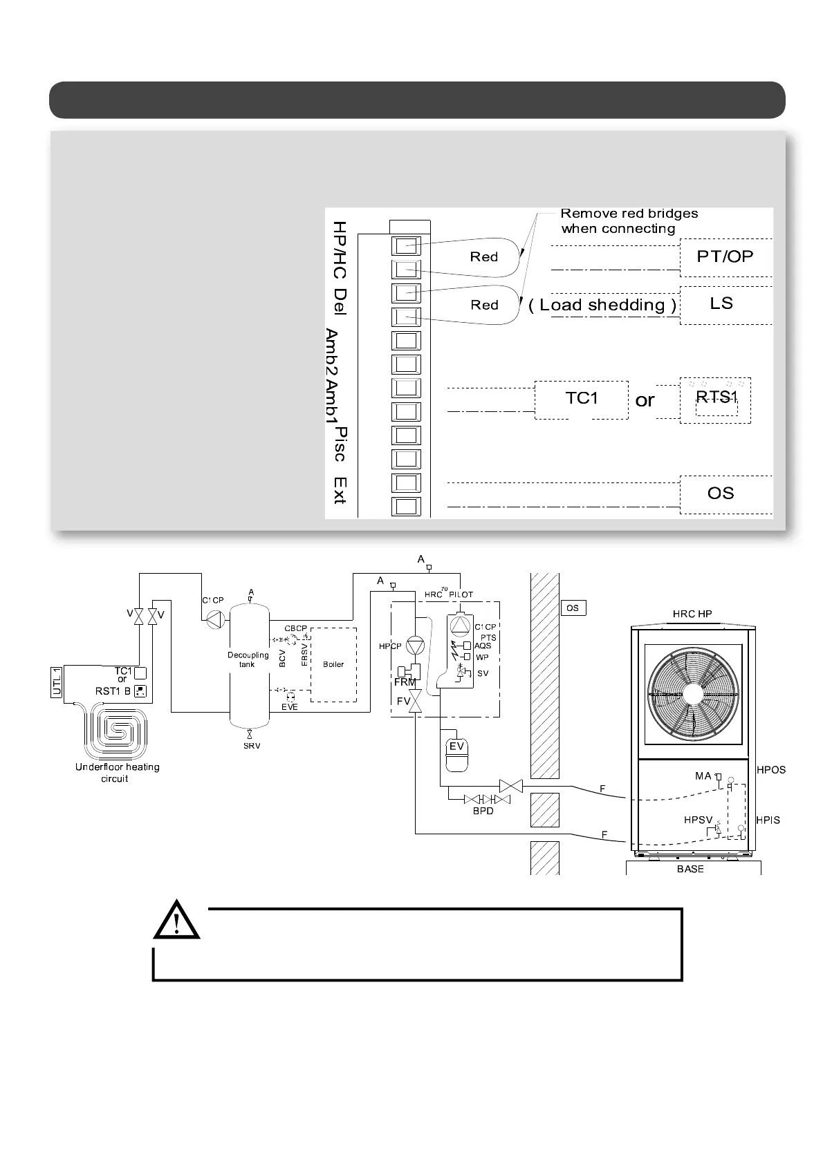
The two under oor temperature limiters (UTL1 & UTL2) MUST be
connected to terminals 1-2 and 4-5 (see § «Under oor heating circuit
application»)
Hydraulic schematic diagram -1 UNDERFLOOR HEATING CIRCUIT- -pool possible- +
boiler
HPCP = circulator pump for Heat Pump circuit
C1CP = circulator pump for heating circuit 1
FRM = Heat Pump circuit ow rate monitor
SV = 3-bar safety valve
A = Air valve
PTS = HRC
70
Pilot temperature sensor (or outgoing water sensor OW)
AQS = 110°C safety aquastat with manual reset
WP = water pressure sensor
SRV = sludge removal valve
FV = lter valve for Heat Pump circuit
V = stop valves
EV = expansion vessel
BPD = back ow prevention device
F = exible hose for Heat Pump connection
MAV = manual air valve
HPSV = Heat Pump safety valve set to 2.5 bar
HPIWS = Heat Pump incoming water sensor
HPOWS = Heat Pump outgoing water sensor
EBCP = existing boiler circulator pump
EVE = expansion vessel for existing installation
BSV = existing boiler safety valve
OS = Heat Pump HRC
70
Pilot outdoor temperature
sensor
TC1 = heating circuit 1 room thermostat
or RTS1 = room temperature sensor with display for heating
circuit 1 (available to order)
UTL1 = circuit 1 under oor temperature limiter
UTL2 = temperature limiting safety device for the heat
pump circulator pump
FRM SP = ow rate monitor for swimming pool circuit
S pool = swimming pool sensor (optional extra included in
swimming pool kit)
C pool = swimming pool circuit circulator pump
3WV = 3-way valve for radiator circuit (winter) or swimming pool circuit
(summer)
BCV = boiler check valve