- INSTALLER 7 & 11kW HRC
70
HIGH TEMPERATURE HEAT PUMP
-
16
3.3 - Installation advice for diff erent
types of transmitters and diff erent
uses
If using thermostatic valves on radiators or underfl oor heating
loops it is MANDATORY to t the 50-litre ‘‘ONIX 50 CF8’’ bu er
tank (Ref. 422013) on the heat pump circuit.
Thermostatic valves: these valves must primarily be used for
premises which receive high quantities of free calories from
sunlight.
In an installation where only thermostatic valves are used there
must be a bypass function in place (e.g. a di erential valve).
It is forbidden to couple a thermostatic ambience control
(sensor or thermostat) with radiators where thermostatic valves
are tted, in the same room.
In order to ensure full satisfaction from your room thermostat is
is essential to follow the installation and assembly instructions
when setting it up.
Thermostatic valves =
MANDATORY buff er tank
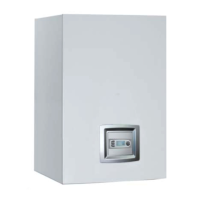
Only possible when coupling with a radiator
circuit
3.3.2 - For domestic hot water
The domestic water circuit must be installed in compliance with
regulations and best practices. It is particularly important to
observe the following instructions:
• A pressure relief valve must be tted onto the cold water inlet on
the tank
• Do not t a shut-o valve between the pressure relief valve and
the tank.
NB : the pressure relief valve may let out a small amount of water
when the DHW is being reheated: this is normal.
• In order to prevent this run-off if the pressure exceeds 4 bar:
- Fit a pressure reducer on the cold water inlet
- Fit a DHW expansion vessel between the pressure relief
It is mandatory to fi t a 50-litre decoupling tank and a circulator
pump for the domestic water circuit.
Domestic hot water can be produced by the Pilot. The domestic
hot water tank is heated by a primary water circuit connected to
the Pilot (circuit n°2)( Accessory: DHW sensor, Ref. 710029).
It is important to equip the hot water tank with a
suitably powerful heat exchanger (minimum 36kW).
To ensure eff ective coupling with the Heat Pump the surface of
the water tank’s primary heat exchanger must be at least 1.4m².
Both of these aquastats cut off the power supply to the underfl oor
heating circulator pump on circuits 1 (
HPCP 1) and 2 (HPCP 2) in
case of abnormally high temperatures on the underfl oor heating
circuit.
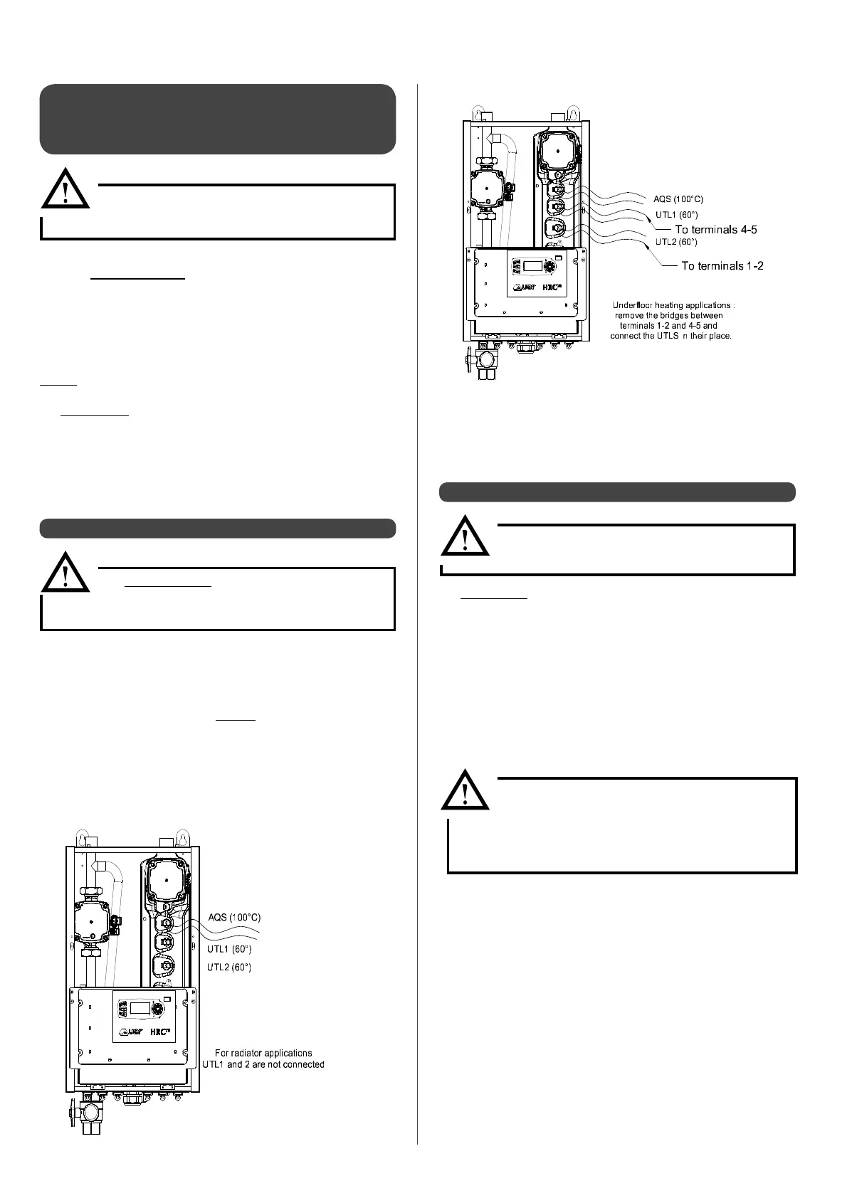
3.3.1 - For underfl oor heating circuits
It is MANDATORY to connect the two
underfl oor heating temperature limiters on
terminals 1-2 and 4-5
No buff er volume need be added as long as an underfl oor heating
loop without thermostatic valves is maintained. This loop without
thermostatic valves enables suffi cient heat reserve for heat pump
de-icing cycles as well as enough inertia to eliminate short cycles.
Otherwise, a 50-litre buff er tank MUST be added to the Heat
Pump return fl ow.
• Adjust setting 207 to a temperature equal to or below 50°C (see
‘‘Setting operating parametres’’).
• Replace the electrical bridges between terminals 1-2 and 4-5 by
the underfl oor heating temperature limiters (UTL 1 and UTL2)
which are supplied with the appliance.
Using a water tank where the primary heat
exchanger is around 36kW (1.5m²) can lead to
Heat Pump malfunction because of on / off cycles
which are too long.