- INSTALLER 7 & 11kW HRC
70
HIGH TEMPERATURE HEAT PUMP
MANUAL -
65
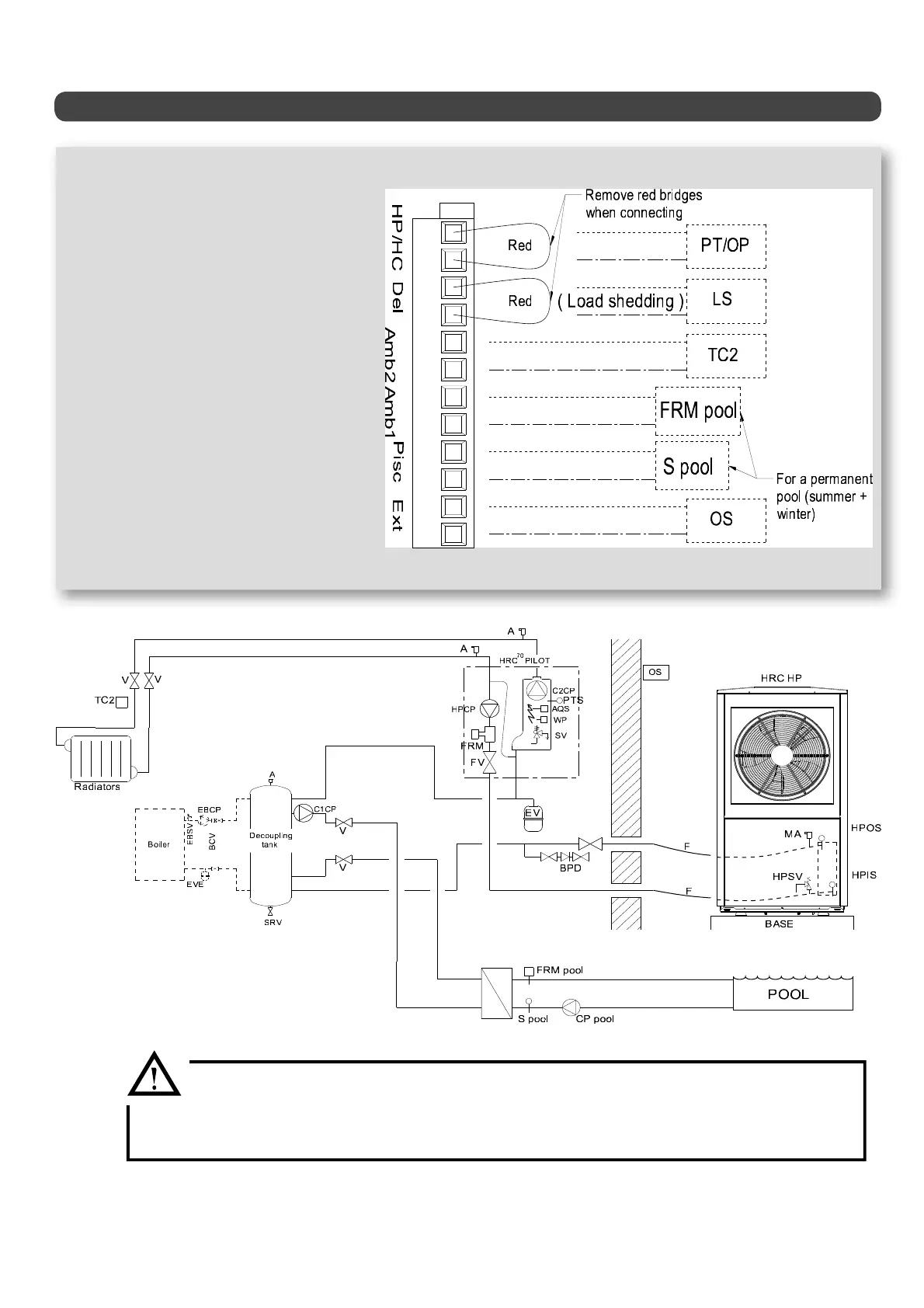
Hydraulic schematic diagram -1 RADIATOR CIRCUIT + PERMANENT POOL-
HPCP = circulator pump for Heat Pump circuit
C1CP = circulator pump for pool
C2CP = circulator pump for heating circuit
FRM = Heat Pump circuit ow rate monitor
SV = 3-bar safety valve
A = Air valve
PTS = HRC
70
Pilot temperature sensor (or outgoing water
sensor OW)
AQS = 110°C safety aquastat with manual reset
WP = water pressure sensor
SRV = sludge removal valve
FV = lter valve for Heat Pump circuit
V = stop valves
EV = expansion vessel
BPD = back ow prevention device
F = exible hose for Heat Pump connection
MAV = manual air valve
HPSV = Heat Pump safety valve set to 2.5 bar
HPIWS = Heat Pump incoming water sensor
HPOWS = Heat Pump outgoing water sensor
EBCP = existing boiler circulator pump
EVE = expansion vessel for existing installation
BSV = existing boiler safety valve
OS = Heat Pump HRC
70
Pilot outdoor temperature sensor
TC2 = heating circuit 2 room thermostat (optional)
FRM SP = ow rate monitor for swimming pool circuit
S pool = swimming pool sensor (optional extra included in
swimming pool kit)
C pool = swimming pool circuit circulator pump
• Disconnect the HRC Pilot heating circulator pump, which is pre-connected at the factory
on terminals 5 and 6.
• Reconnect to terminals 2 and 3.
• Next connect C1CP for the swimming pool to terminals 5 and 6.