- INSTALLER 7 & 11kW HRC
70
HIGH TEMPERATURE HEAT PUMP
-
38
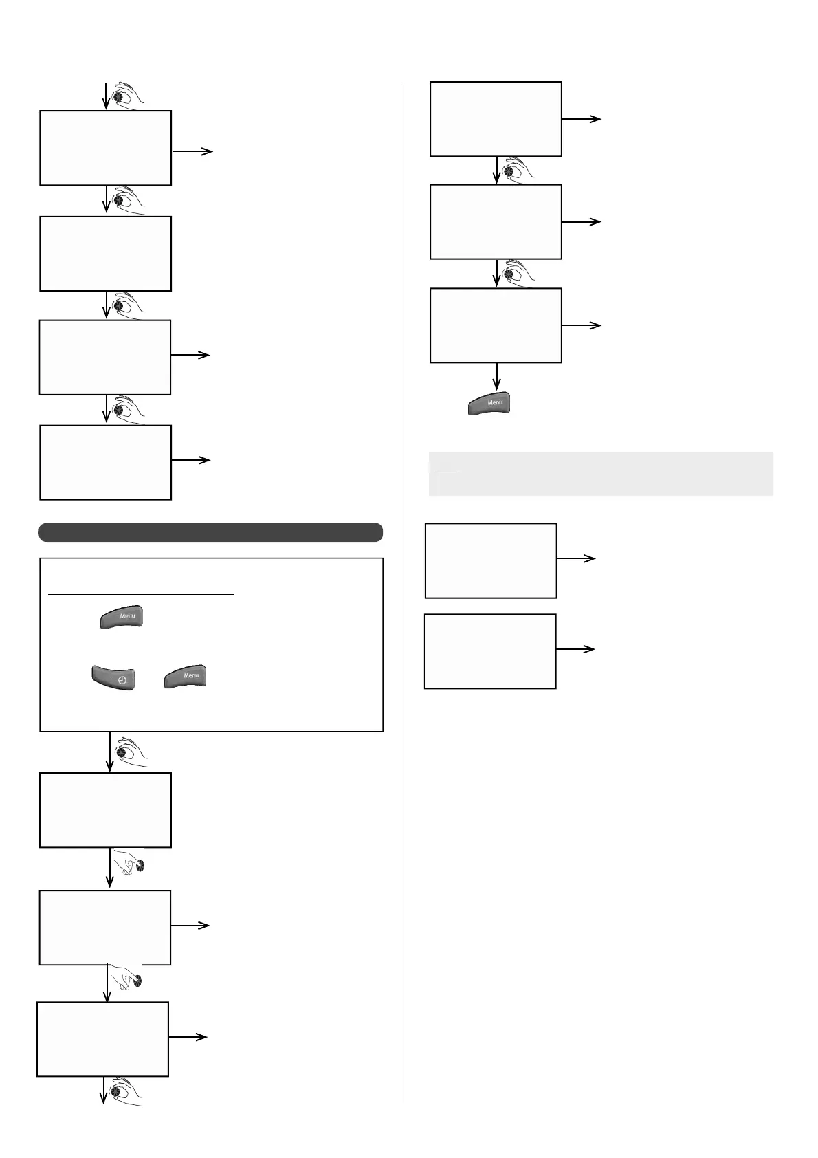
6.5.2 - Accessing calculated data
h e a t cu r v 1
6 2.0 °C
Target temperature at Heat
Pump inlet (where there is
only one circuit)
example
sh e d d in g
2
sw i m . p o o l
2 3 .5 °C
f l o w
0
Pt / o p t
0
Load shedding status (0 = load
shedding in progress, 1 = no
load shedding)
Swimming pool circuit water
temperature
Load shedding status for peak
and o -peak times (0 = load
shedding in progress, 1 = no
load shedding)
example
example
example
da t a ca l c .
Accessing the Installer Menu:
• Press
• Turn the dial until the screen displays
"INST. MENU"
• Press
and at the same time
• Keep them held down simultaneously for 3 sec.
T r r C OM P 1
0 0: 0 7
Time period between 2 start-
ups for the compressor
example
T S R C OM P 1
0 0: 0 3 h
T R S C OM P 1
0 0: 0 3 h
t m o d CO M P 1
0 0: 0 4 h
Minimum stopping time for
compressor 1
Minimum running time for
compressor 1
Time delay before compressor
1 engages
example
example
example
• Press
at any time to return to the data cALC. screen.
N.B: If 2 circuits are con gured, the heating curve is displayed
for each circuit
h e a t cu r v 1
6 2.0 °C
Circuit 1 target temperature at
Heat Pump inlet (if 2 circuits)
example
h e a t cu r v 2
5 7.0 °C
Circuit 2 target temperature at
Heat Pump circuit (if 2 circuits)
example