- INSTALLER 7 & 11kW HRC
70
HIGH TEMPERATURE HEAT PUMP
-
54
A2.2 - HRC
70
Pilot
Max. current re uirements
0 to 6kW three phase or single
phase
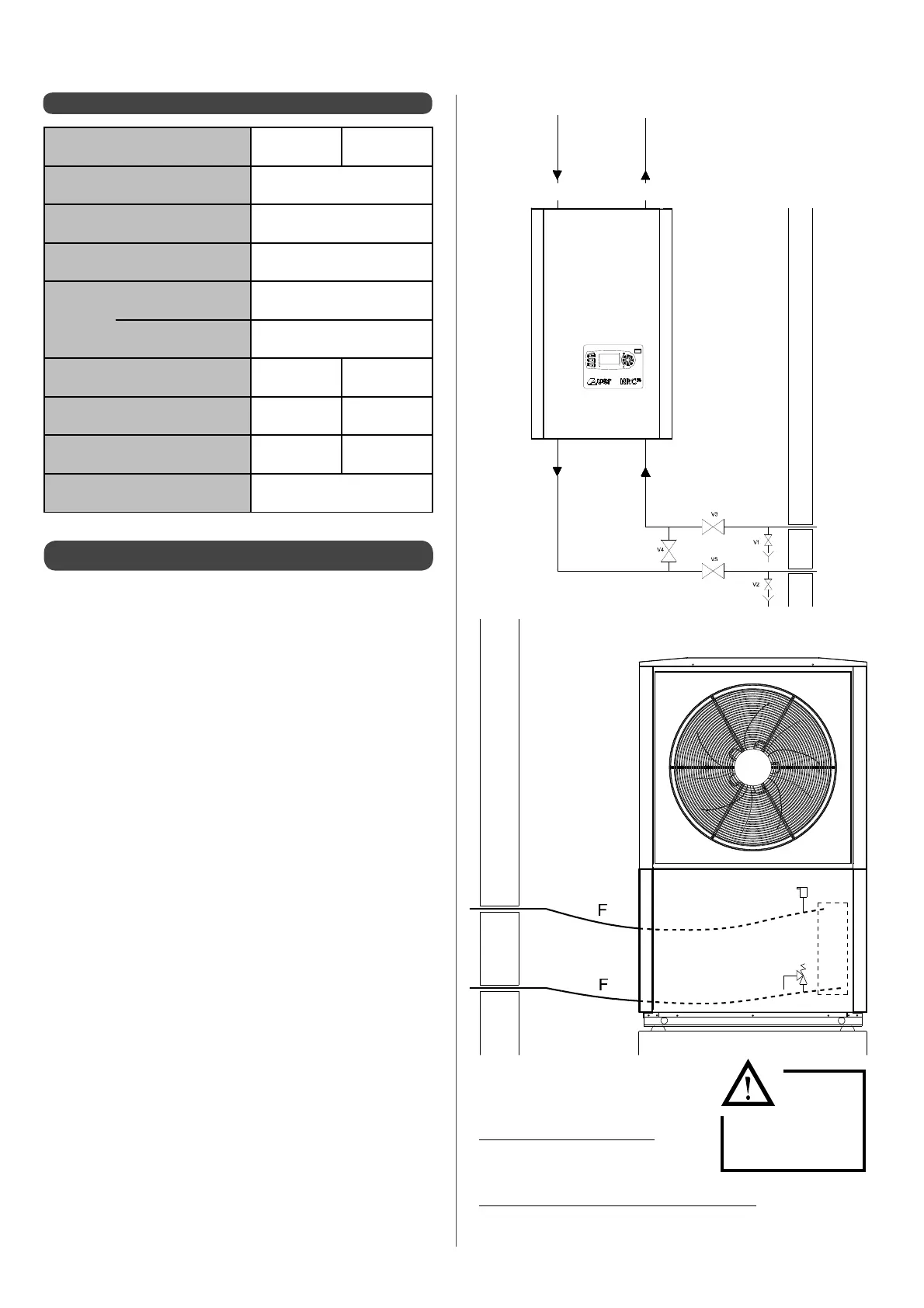
Diagram for draining equipment
70
70
A3 - Frost protection
In cases where the HRC
70
Heat Pump cannot run (outdoor
temperature outside the operating range) if a back-up source
is authorised to run (boiler or electrical) it will automatically
be protected from frost and ice because the circulator pump
will run and extract heat from the heating circuit, which has its
temperature maintained either by the HRC
70
Pilot electrical back-
up or by boiler back-up.
The water temperature remains at 5°C or over.
In all cases the piping must be properly insulated.
Underground piping should also be installed within protective
guttering.
However, for installations without a back-up source or the
Heat
Pump or Pilot being switched o during the winter period (e.g:
stopping accidentally, use in a second home etc...), it will be
necessary to provide additional protection against frost and ice.
Apply glycol to the heating circuit (with a minimum concentration
of 25% glycol) or make sure you have the hydraulic circuit
draining measures in place for the HRC
70
Heat Pump and its
accessories, as explained below.
HRC
70
Pilot
HRC
70
Heat Pump
V1 - V2 : Draining valves
V3 - V4 - V5 : Isolating valves
When running normally:
• V1 - V2 and V4 are closed
• V3 and V5 are open
In case of being switched o in winter:
• V3 and V5 are closed
• V1 - V2 and V4 are open
Ensure
that
the HRC
70
Heat
Pump is drained