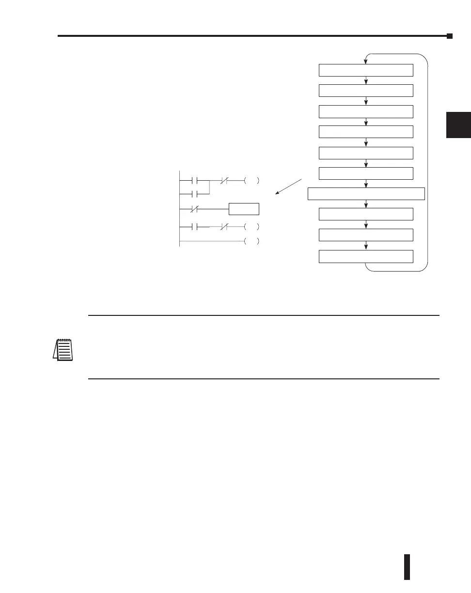
Solve Application Program
The CPU evaluates each instruction in the application
program during this segment of the scan cycle. The
instructions define the relationship between input
conditions and the system outputs.
The CPU begins with the first rung of the ladder
program, evaluating it from left to right and from top to
bottom. It continues, rung by rung, until it encounters
the END coil instruction. At that point, a new image for
the outputs is complete.
The internal control relays (C), the stages (S), and the
variable memory (V) are also updated in this segment.
You may recall the CPU may have obtained and stored forcing information when it serviced
the peripheral devices. If any I/O points or memory data have been forced, the output image
register also contains this information.
NOTE: If an output point was used in the application program, the results of the program solution will
overwrite any forcing information that was stored. For example, if Y0 was forced on by the programming
device, and a rung containing Y0 was evaluated such that Y0 should be turned off, then the output image
register will show that Y0 should be off. Of course, you can force output points that are not used in the
application program. In this case, the point remains forced because there is no solution that results from
the application program execution.
Solve PID Loop Equations
The DL260 CPU can process up to 16 PID loops and the DL250–1 can process up to 4
PID loops. The loop calculations are run as a separate task from the ladder program
execution, immediately following it. Only loops which have been configured are calculated,
and then only according to a built-in loop scheduler. The sample time (calculation interval) of
each loop is programmable. Please refer to Chapter 8, PID Loop Operation, for more on the
effects of PID loop calculation on the overall CPU scan time.
Write Outputs
Once the application program has solved the instruction logic and constructed the output
image register, the CPU writes the contents of the output image register to the corresponding
output points located in the local CPU base or the local expansion bases. Remember, the
CPU also made sure any forcing operation changes were stored in the output image register,
so the forced points get updated with the status specified earlier.
DL205 User Manual, 4th Edition, Rev. B
3–25
Chapter 3: CPU Specifications and Operations
1
2
3
4
5
6
7
8
9
10
11
12
13
14
A
B
C
D
Read Inputs
Read Inputs from Specialty I/O
Solve the Application Program
Write Outputs
Diagnostics
Service Peripherals, Force I/O
Write Outputs to Specialty I/O
CPU Bus Communication
Update Clock, Special Relays
Solve PID equations (DL250-1/DL260)
X0 X1 Y0
OUT
C0
C100
LD
K10
X5 X10 Y3
OUT
END

 Loading...

