DL205 User Manual, 4th Edition, Rev. B
Chapter 4: System Design and Configuration
1
2
3
4
5
6
7
8
9
10
11
12
13
14
A
B
C
D
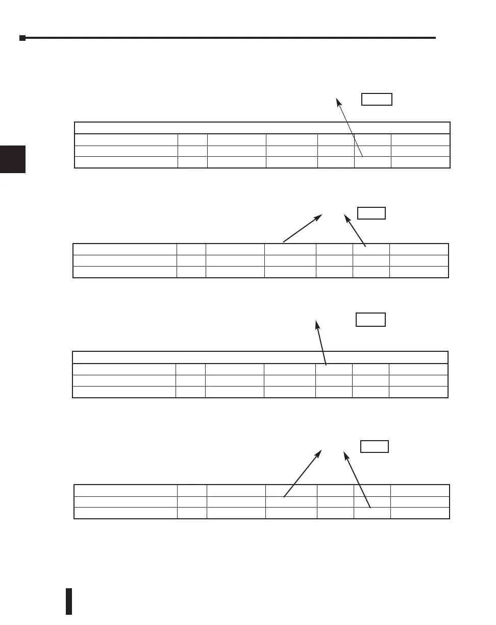
Example 1: V2100 584/984 Mode
Find the Modbus address for User V location
V2100.
1. Find V memory in the table
2. Convert V2100 into decimal (1088).
3. Add the Modbus starting address for the mode (40001).
Example 2: Y20 584/984 Mode
Find the Modbus address for output Y20.
1. Find Y outputs in the table.
2. Convert Y20 into decimal (16).
3. Add the starting address for the range (2048).
4. Add the Modbus address for the mode (1).
Example 3: T10 Current Value 484 Mode
Find the Modbus address to obtain the
current value from Timer T10.
1. Find Timer Current Values in the table.
2. Convert T10 into decimal (8).
3. Add the Modbus starting address for the mode (3001).
Example 4: C54 584/984 Mode
Find the Modbus address for Control Relay
C54.
1. Find Control Relays in the table.
2. Convert C54 into decimal (44).
3. Add the starting address for the range (3072).
4. Add the Modbus address for the mode (1).
Determining the
DDiirreecctt
NET Address
Addressing the memory types for DirectNET slaves is very easy. Use the ordinary native
address of the slave device itself. To access a slave PLC’s memory address V2000 via
DirectNET, for example, the network master will request V2000 from the slave.
PLC Address (Dec.) + Mode Address
V2100 = 1088 decimal
1088 + 40001 =
41089
For Word Data Types... PLC Address (Dec.) + Appropriate Mode Address
Timer Current Value (V) 128 V0 - V177 0 - 127 3001 30001 Input Register
Counter Current Value (V) 128 V1000 - V1177 512 - 639 3001 30001 Input Register
V Memory, User Data (V) 1024 V2000 - V3777
1024 - 2047
4001 40001 Hold Register
PLC Addr. (Dec.) + Start Address + Mode
Y20 = 16 decimal
16 + 2048 + 1 =
2065
Outputs (Y) 320 Y0 - Y477 2048 - 2367 1 1 Coil
Control Relays (CR) 256 C0 - C377 3072 - 3551 1 1 Coil
Timer Contacts (T) 128 T0 - T177 6144 - 6271 1 1 Coil
For Word Data Types... PLC Address (Dec.) + Appropriate Mode Address
Timer Current Value (V) 128 V0 - V177 0 - 127 3001 30001 Input Register
Counter Current Value (V) 128 V1000 - V1177 512 - 639 3001 30001 Input Register
V Memory, User Data (V) 1024 V2000 - V3777 1024 - 2047 4001 40001 Hold Register
PLC Address (Dec.) + Mode Address
TA10 = 8 decimal
8 + 3001 =
3009
Outputs (Y) 320 Y0 - Y477 2048 - 2367 1 1 Coil
Control Relays (CR) 256 C0 - C377 3072 - 3551 1 1 Coil
Timer Contacts (T) 128 T0 - T177 6144 - 6271 1 1 Coil
PLC Addr. (Dec.) + Start Address + Mode
C54 = 44 decimal
44 + 3072 + 1 =
3117
4–40

 Loading...

