DL205 User Manual, 4th Edition, Rev. B
2–45
Chapter 2: Installation, Wiring and Specifications
1
2
3
4
5
6
7
8
9
10
11
12
13
14
A
B
C
D
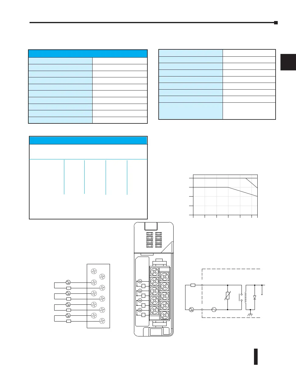
D2–04TRS, Relay Output
NC
NC
C0
C1
C2
C3
0
1
2
3
L
L
L
L
5--30 VDC
NC
NC
C0
0
C1
1
C2
2
C3
3
5-240VAC
4A 50/ 60Hz
D2-- 04T R S
OUT RELA Y
D2--04TR S
0
1
2
3
L
5--30V DC
10mA- -4A
L
L
L
5--240 VAC
0
1
2
3
4
0
10 20 30 40 50 55
Ambient Te mperature (˚C/˚F)
32
50 68 86 104 122 131
C˚
F˚
Points
2A /
Pt.
3A /
Pt.
4A /
Pt.
COM
OUTP UT
To L E D
Internal module circuitry
6.3A
5--240 VAC
L
5--30 VDC
Derating Chart
D2-04TRS Relay Output
Outputs per Module
4
Outputs Points Consumed
8
(only 1st 4pts. are used)
Commons per Module
4 (isolated)
Output Type
Relay, form A (SPST)
Operating Voltage
5-30 VDC / 5-240 VAC
Peak Voltage
30 VDC, 264 VAC
ON Voltage Drop
0.72 VDC maximum
AC Frequency
47 to 63 Hz
Minimum Load Current
10 mA
Max Load Current (resistive)
4A/point; 8A/module (resistive)
Max Leakage Current
0.1 mA @ 264 VAC
Max Inrush Current
5A for < 10 ms
Base Power Required 5VDC
250 mA
OFF to ON Response
10 ms
ON to OFF Response
10 ms
Terminal Type (included)
Removable; D2-8IOCON
Status Indicator
Logic side
Weight
2.8 oz. (80 g)
Fuses
1 per point
6.3A slow blow, replaceable
Order D2-FUSE-3 (5 per pack)
Typical Relay Life (Operations)
Voltage &Load Current
Type of Load 1A 2A 3A 4A
24 VDC Resistive 500k 200k 100k 50k
24 VDC Solenoid 100k 40k –– –
110 VAC Resistive 500k 250k 150k 100k
110 VAC Solenoid 200k 100k 50k –
220 VAC Resistive 350k 150k 100k 50k
220 VAC Solenoid 100k 50k –– ––
At 24 VDC, solenoid (inductive) loads over 2A cannot be used.
At 100 VAC, solenoid (inductive) loads over 3A cannot be used.
At 220 VAC, solenoid (inductive) loads over 2A cannot be used.

 Loading...

