DL205 User Manual, 4th Edition, Rev. B
5–49
Chapter 5: Standard RLL Instructions - Timer, Counter and Shift Register
1
2
3
4
5
6
7
8
9
10
11
12
13
14
A
B
C
D
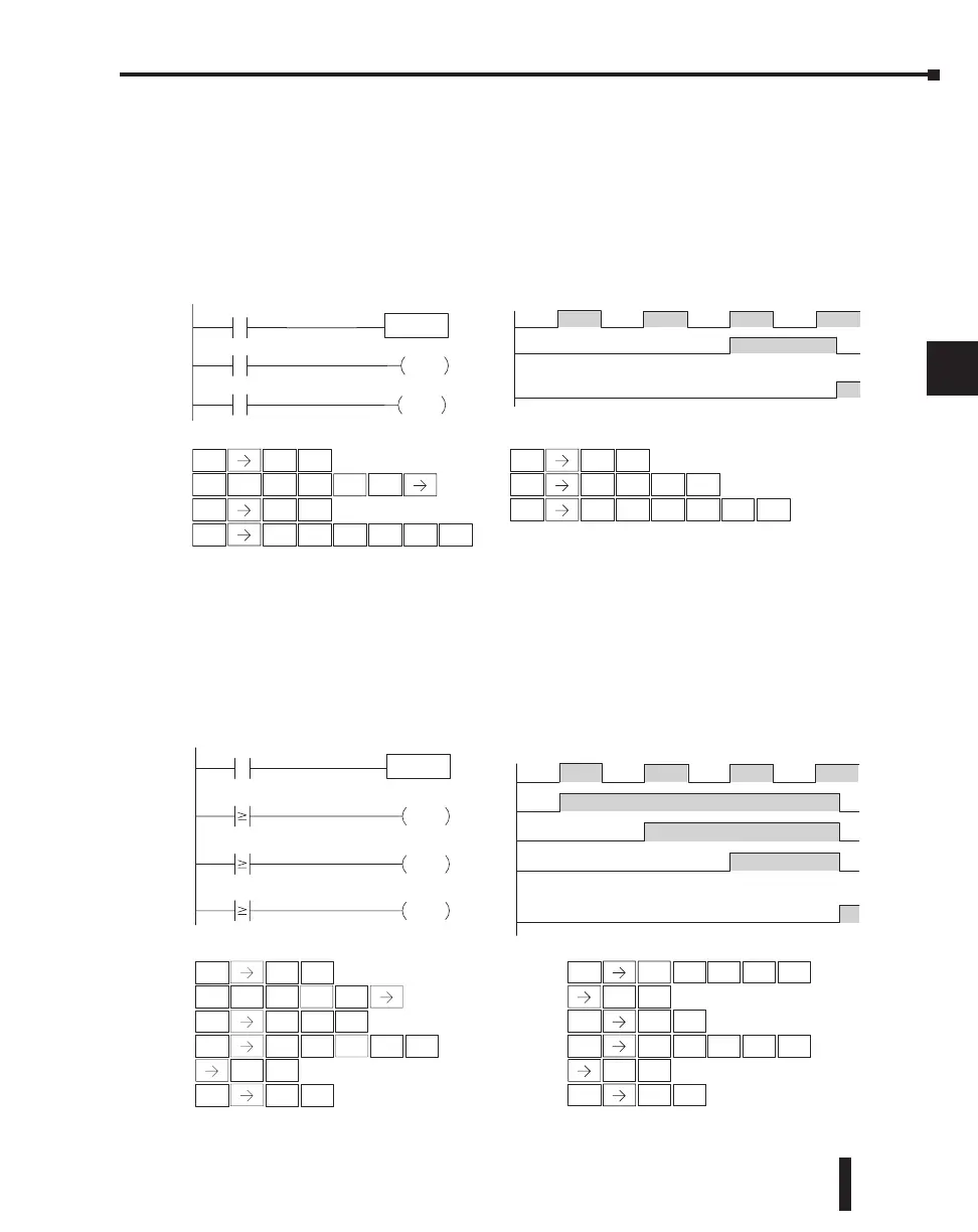
Stage Counter Example Using Discrete Status Bits
In the following example, when X1 makes an off to on transition, stage counter CT7 will
increment by one. When the current value reaches 3, the counter status bit CT7 will turn on
and energize Y7. The counter status bit CT7 will remain on until the counter is reset using
the RST instruction. When the counter is reset, the counter status bit will turn off and the
counter current value will be 0. The current value for counter CT7 will be held in V-memory
location V1007.
Stage Counter Example Using Comparative Contacts
In the following example, when X1 makes an off to on transition, counter CT2 will
increment by one. Comparative contacts are used to energize Y3, Y4, and Y5 at different
counts. Although this is not shown in the example, when the counter is reset using the Reset
instruction, the counter status bit will turn off and the current value will be 0. The current
value for counter CT2 will be held in V-memory location V1002.
3
D
7
H
Handheld Programmer Keystrokes
X1
C5
CT7
SGCNT CT7
K3
RST
X1
Y7
12340
Current
Value
RST
C
T7
CT7
Y7
OUT
Counting diagram
DirectSOFT
STR
$
1
B
ENT
CNT
GY
STR
$
SHFT ENT
OUT
GX
ENT
H
2
C
MLR
T
7
H
STR
$
SHFT ENT
2
C
5
F
RST
S
SHFT
2
C
7
H
ENT
SHFT
RST
S
6
G
SHFT
ENT
Handheld Programmer Keystrokes (cont)
SHFT
SHFT
SHFT
MLR
T
7
Handheld Programmer Keystrokes
X1
X1
Y3
12 340
Current
Value
Counting diagram
CTA2 K1
CTA2 K2
CTA2 K3
Y4
OUT
Y3
OUT
Y5
OUT
Y4
Y5
SGCNT CT2
K10
DirectSOFT
Handheld Programmer Keystrokes (cont)
STR
$
1
B
ENT
CNT
GY
SHFT
RST
S
6
G
SHFT
ENT
2
C
1
B
0
A
STR
$
SHFT
1
B
ENT
OUT
GX
ENT
3
D
MLR
T
2
C
2
C
STR
$
SHFT
ENT
OUT
GX
ENT
2
C
4
E
STR
$
SHFT
2
C
ENT
OUT
GX
ENT
3
D
5
F
MLR
T
2
C
2
C
MLR
T
2
C
SHFT
SHFT
SHFT
RST
CT2

 Loading...

