DL205 User Manual, 4th Edition, Rev. B
1–5
Chapter 1: Getting Started
1
2
3
4
5
6
7
8
9
10
11
12
13
14
A
B
C
D
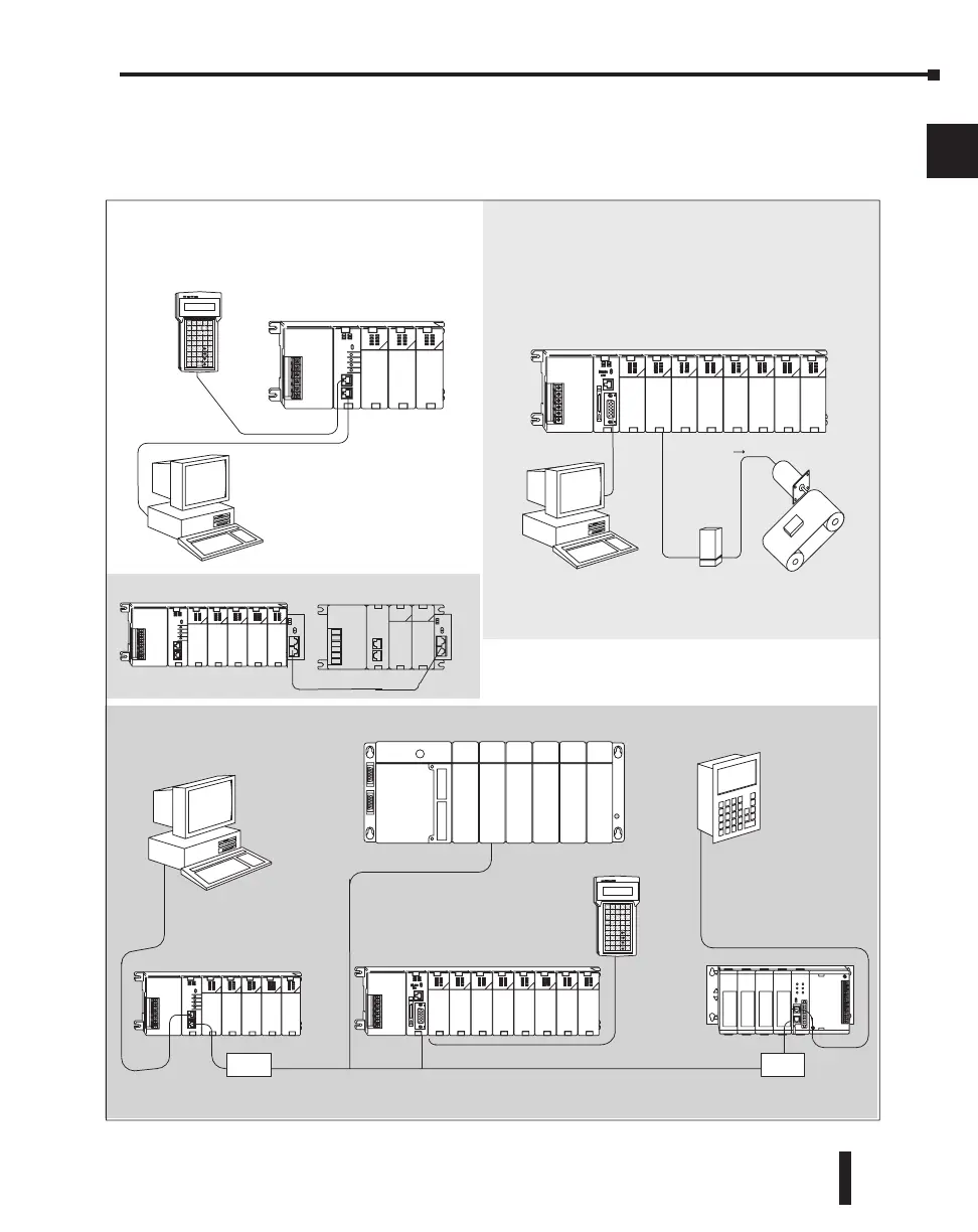
DL205 System Diagrams
The diagram below shows the major components and configurations of the DL205 system.
The next two pages show specific components for building your system.
Getting Started
Networking
RS232C
(max.50ft/16.2m)
RS232C
(max.50ft/16.2m)
(max.
6.5ft / 2m)
Handheld Programmer
Operator Interface
Programming or
Computer Interface
Simple Motion Control
Flexible solutions in one package
High-speed counting (up to 100 KHz)
Pulse train output (up to 50KHz
High–speed Edge timing
Machine
Control
Packaging
Conveyors
Elevators
Programming or
Computer Interface
RS232C
(max.50ft/16.2m)
Handheld
Programmer
DL240
RS232/422
Convertor
RS232/422
Convertor
Simple programming
through the RLL Program
DL260 with H2–CTRIO(2) High Speed I/O Module
DL240
DL250–1 or DL260
DL305
Pulse
Output
Drive
Amplifier
Stepper Motor
Local I/O Expansion
DCM

 Loading...

