Chapter 2: Installation, Wiring and Specifications
2–5
DL205 User Manual, 4th Edition, Rev. B
Mounting Guidelines
Before installing the PLC system you will need to know the dimensions of the components
considered. The diagrams on the following pages provide the component dimensions to use
in defining your enclosure specifications. Remember to leave room for potential expansion.
NOTE: If you are using other components in your system, refer to the appropriate manual to determine
how those units can affect mounting dimensions.
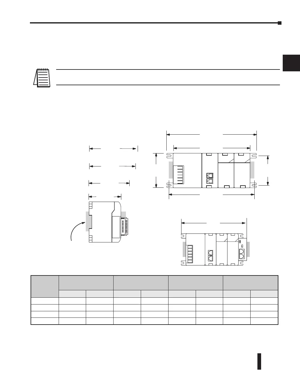
Base Dimensions
The following information shows the proper mounting dimensions. The height dimension is
the same for all bases. The depth varies depending on your choice of I/O module. The length
varies as the number of slots increase. Make sure you have followed the installation guidelines
for proper spacing.
1
2
3
4
5
6
7
8
9
10
11
12
13
14
A
B
C
D
Base
A
(Base Total Width)
B
(Mounting Hole)
C
(Component Width)
D
(Width with Exp. Unit)
Inches Millimeters Inches Millimeters Inches Millimeters Inches Millimeters
3-slot 6.77” 172mm 6.41” 163mm 5.8” 148mm 7.24” 184mm
4-slot 7.99” 203mm 7.63” 194mm 7.04” 179mm 8.46” 215mm
6-slot 10.43” 265mm 10.07” 256mm 9.48” 241mm 10.90” 277mm
9-slot 14.09” 358mm 13.74” 349mm 13.14” 334mm 14.56” 370mm
B
A
C
2.99”
(76mm)
3.54”
(90mm)
DIN Rail slot. Use rail con forming to
DIN EN 50022.
2.95”
(75mm)
3.62”
(92mm)
12 or 16pt I/O
4 or 8pt . I/O
D
with D2–EM Expansion Unit
4.45”
(113mm)
32pt.
ZIPLink cable or
base exp. unit cable
5.85”
(148mm)
D2–DSCBL–1
on port 2
Mounting depths with:

 Loading...

