DL205 User Manual, 4th Edition, Rev. B
2–28
Chapter 2: Installation, Wiring and Specifications
1
2
3
4
5
6
7
8
9
10
11
12
13
14
A
B
C
D
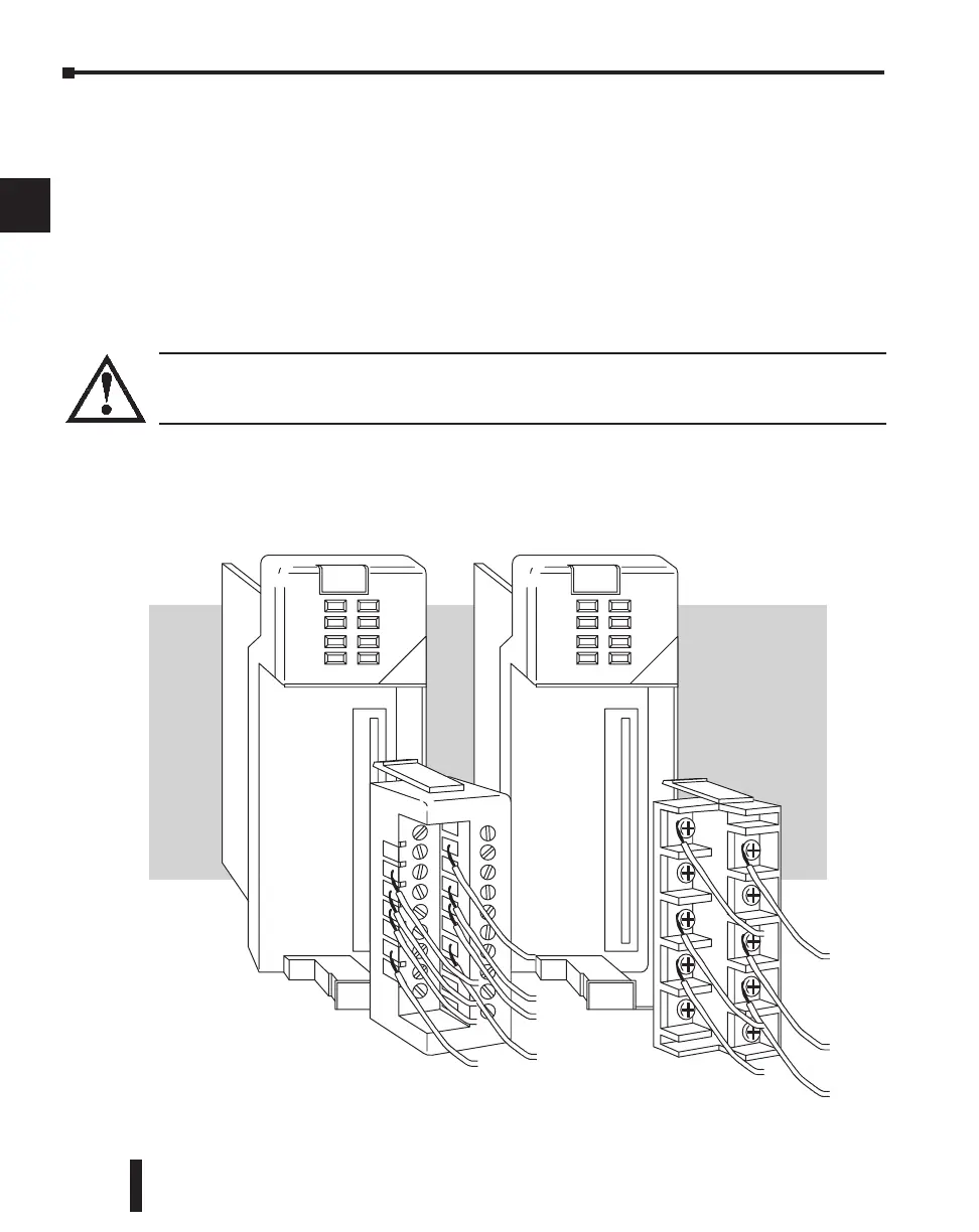
Wiring the Different Module Connectors
There are two types of module connectors for the DL205 I/O. Some modules have normal
screw terminal connectors. Other modules have connectors with recessed screws. The
recessed screws help minimize the risk of someone accidentally touching active wiring.
Both types of connectors can be easily removed. If you examine the connectors closely, you’ll
notice there are squeeze tabs on the top and bottom. To remove the terminal block, press the
squeeze tabs and pull the terminal block away from the module.
We also have DIN rail mounted terminal blocks, DINnectors (refer to our catalog for a
complete listing of all available products). ZIPLinks come with special pre–assembled cables
with the I/O connectors installed and wired.
WARNING: For some modules, field device power may still be present on the terminal block even
though the PLC system is turned off. To minimize the risk of electrical shock, check all field device
power before you remove the connector.

 Loading...

