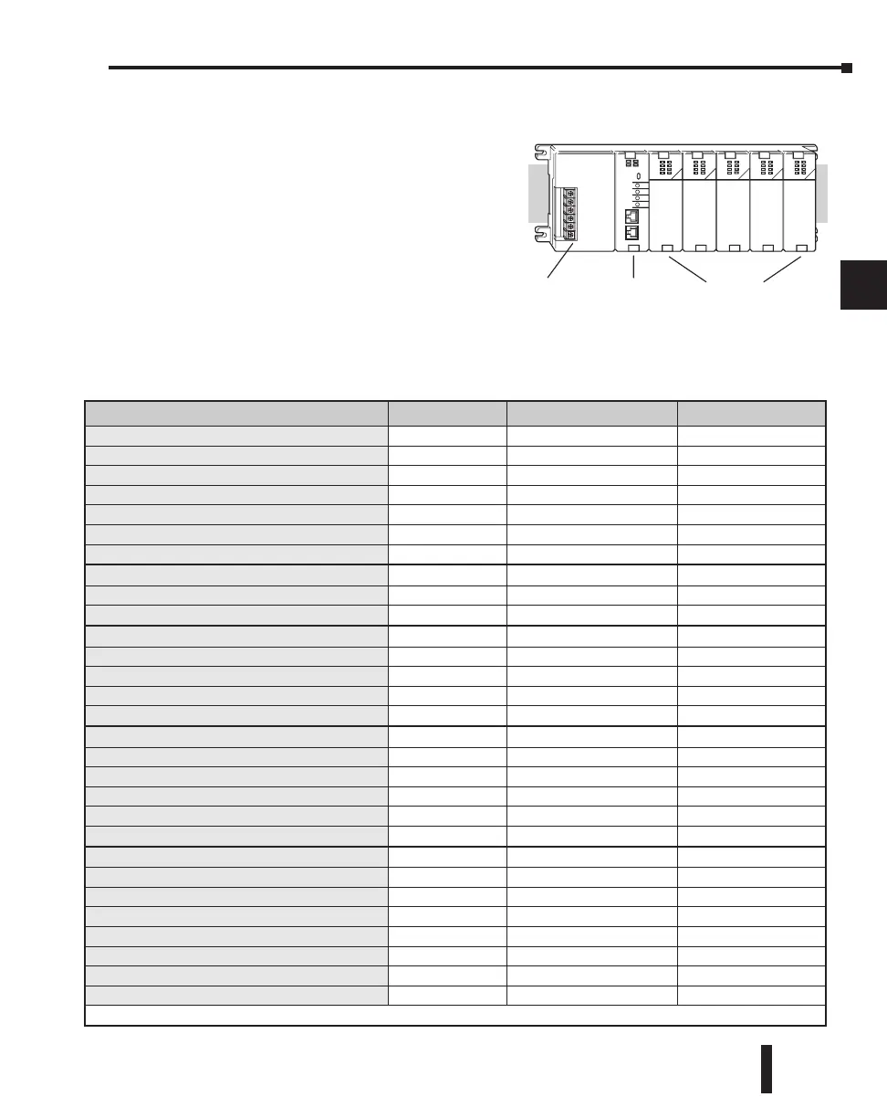
Module Placement
Slot Numbering
The DL205 bases each provide different
numbers of slots for use with the I/O
modules. You may notice the bases refer to
3-slot, 4-slot, etc. One of the slots is
dedicated to the CPU, so you always have
one less I/O slot. For example, you have five
I/O slots with a 6-slot base. The I/O slots
are numbered 0 – 4. The CPU slot always
contains a CPU or a base controller (EBC)
or Remote Slave and is not numbered.
Module Placement Restrictions
The following table lists the valid locations for all types of modules in a DL205 system.
Module/Unit Local CPU Base Local Expansion Base Remote I/O Base
CPUs
CPU Slot Only
DC Input Modules
AC Input Modules
DC Output Modules
AC Output Modules
Relay Output Modules
Analog Input and Output Modules
Local Expansion
Base Expansion Unit
Base Controller Module
CPU Slot Only
Serial Remote I/O
Remote Master
(not Slot O)
Remote Slave Unit
CPU Slot Only
Ethernet Remote Master
(not Slot O)
Ethernet Slave (EBC)
CPU Slot Only
CPU Interface
Ethernet Base Controller
CPU Slot Only CPU Slot Only*
WinPLC
CPU Slot Only
DeviceNet
CPU Slot Only
Profibus
CPU Slot Only
SDS
CPU Slot Only
Specialty Modules
Counter Interface (CTRINT)
Slot 0 Only
Counter I/O (CTRIO)
*
Data Communications
(not Slot O)
Ethernet Communications
(not Slot O)
BASIC CoProcessor
(not Slot O)
Simulator
Filler
*When used in H2–ERM(100) Ethernet Remote I/O systems.
DL205 User Manual, 4th Edition, Rev. B
4–3
Chapter 4: System Design and Configuration
1
2
3
4
5
6
7
8
9
10
11
12
13
14
A
B
C
D
Power Wiring
Connections
CPU Slot
I/O Slots
Slot 0 Slot 1 Slot 2 Slot 3 Slot 4

 Loading...

