Automatic I/O Configuration
The DL205 CPUs automatically detect any installed I/O modules (including specialty
modules) at powerup, and establish the correct I/O configuration and addresses. This applies
to modules located in local and local expansion I/O bases. For most applications, you will
never have to change the configuration.
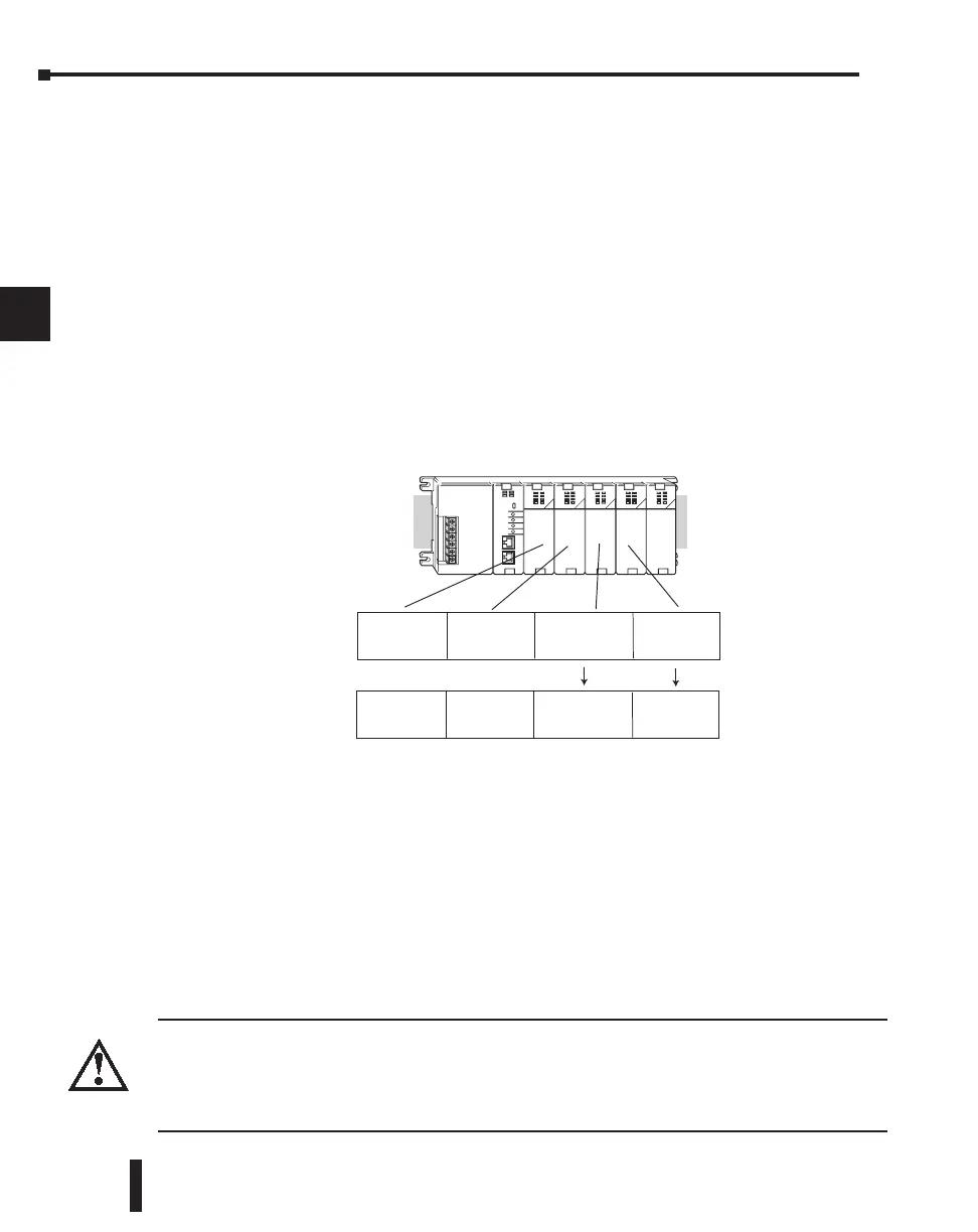
I/O addresses use octal numbering, starting at X0 and Y0 in the slot next to the CPU. The
addresses are assigned in groups of 8 or 16, depending on the number of points for the I/O
module. The discrete input and output modules can be mixed in any order, but there may be
restrictions placed on some specialty modules. The following diagram shows the I/O
numbering convention for an example system.
Both the Handheld Programmer and DirectSOFT provide AUX functions that allow you to
automatically configure the I/O. For example, with the Handheld Programmer AUX 46
executes an automatic configuration, which allows the CPU to examine the installed modules
and determine the I/O configuration and addressing. With DirectSOFT, the PLC Configure
I/O menu option would be used.
Manual I/O Configuration
It may never become necessary, but DL250–1 and DL260 CPUs allow manual I/O address
assignments for any I/O slot(s) in local or local expansion bases. You can manually modify an
auto configuration to match arbitrary I/O numbering. For example, two adjacent input
modules can have starting addresses at X20 and X200. Use DirectSOFT PLC Configure I/O
menu option to assign manual I/O address.
In automatic configuration, the addresses are assigned on 8-point boundaries. Manual
configuration, however, assumes that all modules are at least 16 points, so you can only assign
addresses that are a multiple of 20 (octal). For example, X30 and Y50 are not valid starting
addresses. You can still use 8 point modules, but 16 addresses will be assigned and the upper
eight addresses will be unused.
WARNING: If you manually configure an I/O slot, the I/O addressing for the other modules may change.
This is because the DL250–1 and DL260 CPUs do not allow you to assign duplicate I/O addresses. You
must always correct any I/O configuration errors before you place the CPU in RUN mode. Uncorrected
errors can cause unpredictable machine operation that can result in a risk of personal injury or
damage to equipment.
DL205 User Manual, 4th Edition, Rev. B
4–4
Chapter 4: System Design and Configuration
1
2
3
4
5
6
7
8
9
10
11
12
13
14
A
B
C
D
Slot 0
8pt. Input
X0-X7
Slot 1
16pt. Output
Y0-Y17
Slot 2
16pt. Input
X10-X27
Slot 3
8pt. Input
X30-X37
Slot 0
8pt. Input
X0-X7
Slot 1
16pt. Output
Y0-Y17
Slot 2
16pt. Input
X100-X117
Slot 3
8pt. Input
X20-X27
Automatic
Manual

 Loading...

