DL205 User Manual, 4th Edition, Rev. B
4–55
Chapter 4: System Design and Configuration
1
2
3
4
5
6
7
8
9
10
11
12
13
14
A
B
C
D
• XON/XOFF Flow Control: When this function is enabled, the PLC will send data (PRINT
command) until it receives a XOFF (0x13) Pause transmission command. It will continue to wait
until it then sees a XON (0x11) Resume transmission command. This selection is only available
when the "Non-Sequence(ASCII)" option has been selected and only functions when the PLC is
sending data (not receiving with AIN command).
• RTS Flow Control: When this function is enabled, the PLC will assert the RTS signal(s) of the port
and wait to see the CTS signal(s) go true before sending data (PRINT command). This selection is
only available when the "Non-Sequence(ASCII)" option has been selected and only functions when
the PLC is sending data (not receiving with AIN command).
• Echo Suppression: Select the appropriate radio button based on the wiring configuration used on
port 2.
Then click the button indicated to send the Port configuration to the CPU, and click Close.
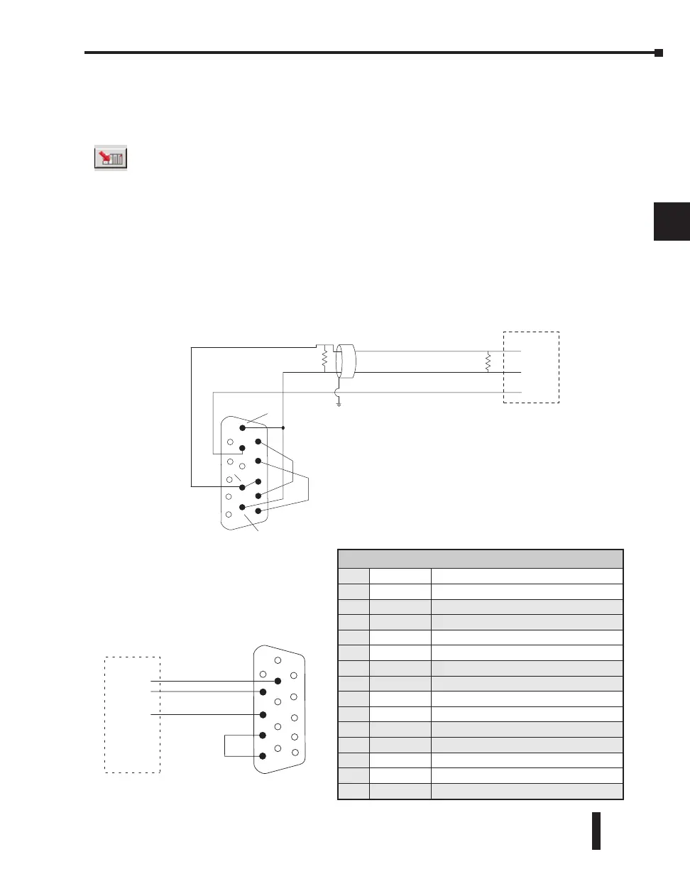
RS–485 Network
RS–485 signals are for long distances (1000 meters max.). Use termination resistors at both
ends of RS–485 network wiring, matching the impedance rating of the cable (between 100
and 500 ohms).
RS–232 Network
RS–232 signals are used for shorter
distances (15 meters max) and
limited to communications between
two devices.
Signal GND
RXD
1
5
10
11
15
TXD
7
2
3
4
TXD
RXD
GND
RTS
CTS
RTS
CTS
6
CPU Port 2
ASCII Device
DL260 CPU Port 2
T ermination
Resistor
Cable: Use AutomationDirect L19954
(Belden 9842) or equivalent
TXD+
TXD–
RXD–
7
10
15
RXD+
0V
6
11
TXD+ / RXD+
TXD– / RXD–
Signal GND
TXD+ / RXD+
TXD– / RXD–
Signal GND
R TS+
R TS–
CTS+
CTS–
ASCII Device
5
1
Port 2 Pin Descriptions (DL260 only)
1
5V 5 VDC
2
TXD2 Transmit Data (RS-232)
3
RXD2 Receive Data (RS-232)
4
RTS2 Ready to Send (RS–232)
5
CTS2 Clear to Send (RS–232)
6
RXD2– Receive Data – (RS–422/RS-485)
7
0V Logic Ground
8
0V Logic Ground
9
TXD2+ Transmit Data + (RS–422/RS–485)
10
TXD2 – Transmit Data – (RS–422/RS–485)
11
RTS2 + Request to Send + (RS–422/RS–485)
12
RTS2 – Request to Send – (RS–422/RS–485)
13
RXD2 + Receive Data + (RS–422/RS–485)
14
CTS2 + Clear to Send + (RS-422/RS–485)
15
CTS2 – Clear to Send – (RS–422/RS–485)

 Loading...

