DL205 User Manual, 4th Edition, Rev. B
2–41
Chapter 2: Installation, Wiring and Specifications
1
2
3
4
5
6
7
8
9
10
11
12
13
14
A
B
C
D
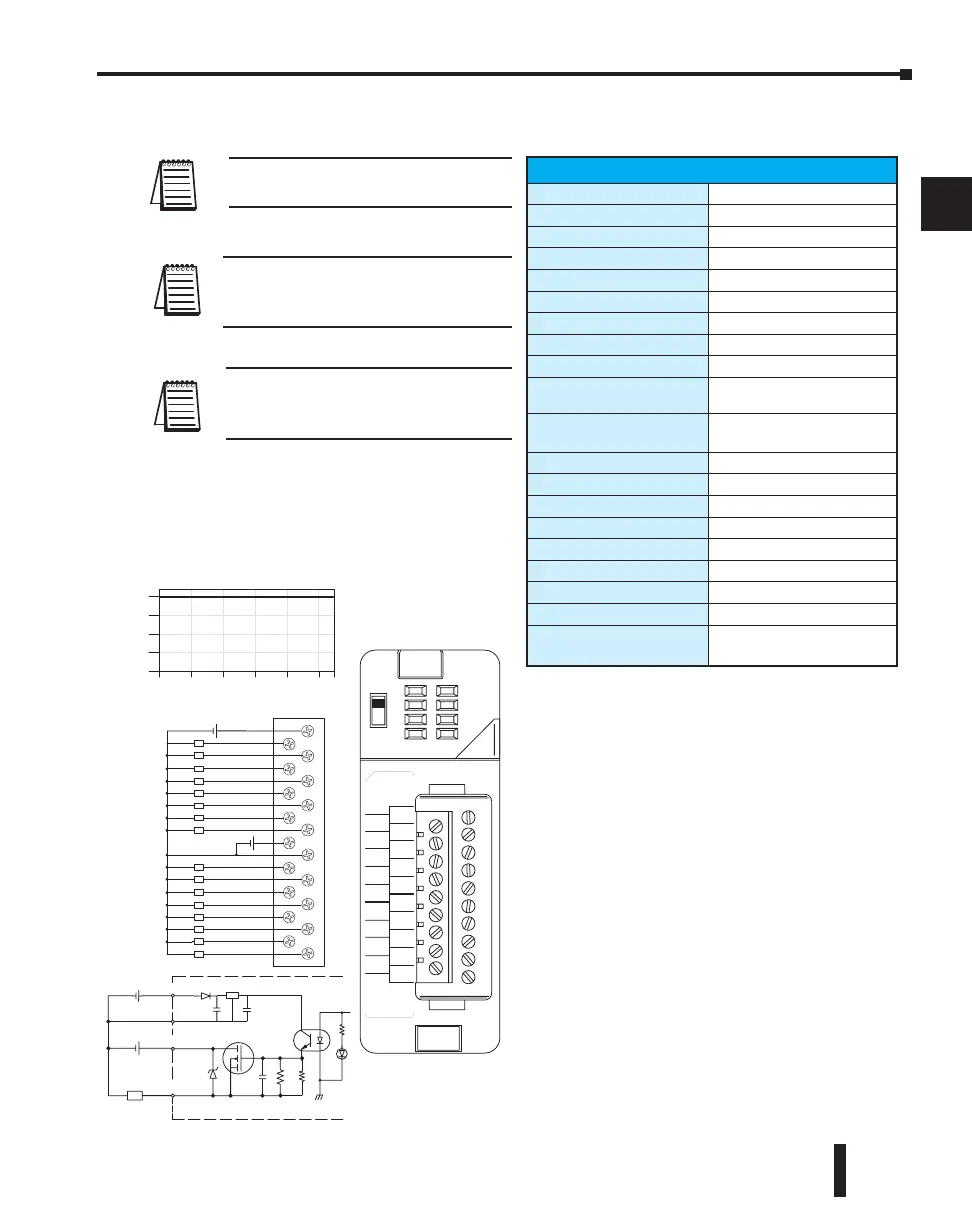
Derating Chart
24VDC
Ambient Temperature (°C/°F)
0
4
8
12
16
Points
0
1
2
3
5
6
7
24V
0
1
2
3
0V
4
5
6
7
4
L
L
L
L
L
L
L
L
L
L
L
L
L
L
L
L
A
B
10.2-26.4
VDC 0.25A
CLASS2
OUT 12-24
F2–16TD2P
VDC
0
1
2
3
4
5
6
7
V1
4
5
6
7
0V
4
5
6
3
2
1
0
24V
3
2
1
0
7
A
B
+
When the A/B switch is in the A position,
the LEDs display the output status of the
module’s first 8 output points. Positon B
displays the output status of the mod-
ule’s second group of 8 output points.
0
10 20 30 40 50 55°C
131°F
32 50 68 86 104 122
V1
12–24VDC
+
24V
V1
L
+–
24VDC
0V
OUTPUT
Reg
12–24VDC
+
Optical
Isolator
F2–16TD2P, DC Output with Fault Protection
NOTE: Supporting Firmware:
D2-250-1 must be V4.80 or later
D2-260 must be V2.60 or later
NOTE: This module does not currently
support Think & Do 8.0. It does not
support Think & Do Live! or Studio.
NOTE: Not supported in D2-230, D2-240
and D2-250 CPUs.
F2-16TD2P DC Output with Fault Protection
Inputs per module
16 (status indication)
Outputs per module
16 (current sourcing)
Commons per module
1
Output type
NMOS FET (open source)
Operating voltage
10.2 -26.4 VDC, external
Peak voltage
40 VDC
AC frequency
N/A
ON voltage drop
0.7 V (output current 0.5 A)
Overcurrent trip
0.6 A min., 1.2A max.
Maximum load current
0.25 A continuous, 0.5 A
peak
Maximum OFF current
Jumper J6 installed: 200 A;
J6 removed: 30 A
Base power required 5V
70 mA
OFF to ON response
0.5 ms
ON to OFF response
0.5 ms
Terminal type
Removable (D2-16IOCON)
Status indicators
Logic Side
Weight
2.0 oz. (25g)
Fuses
None
External DC required
24 VDC /10% @ 50 mA
External DC overvoltage
shutdown
27 V, outputs are restored
when voltage is within limits

 Loading...

