DL205 User Manual, 4th Edition, Rev. B
2–18
Chapter 2: Installation, Wiring and Specifications
1
2
3
4
5
6
7
8
9
10
11
12
13
14
A
B
C
D
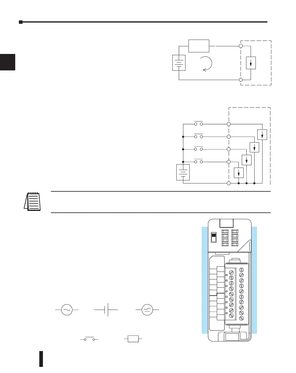
I/O “Common” Terminal Concepts
In order for a PLC I/O circuit to operate,
current must enter at one terminal and exit
at another. Therefore, at least two terminals
are associated with every I/O point. In the
figure to the right, the Input or Output
terminal is the main path for the current.
One additional terminal must provide the
return path to the power supply.
If there was unlimited space and budget for
I/O terminals, every I/O point could have
two dedicated terminals as the figure above
shows. However, providing this level of
flexibility is not practical or even necessary
for most applications. So, most Input or
Output points on PLCs are in groups which
share the return path (called commons). The
figure to the right shows a group (or bank) of
four input points which share a common
return path. In this way, the four inputs
require only five terminals instead of eight.
NOTE: In the circuit above, the current in the common path is 4 times any channel’s input current when all
inputs are energized. This is especially important in output circuits, where heavier gauge wire is
sometimes necessary on commons.
Most DL205 input and output modules group their I/O
points into banks that share a common return path.
The best indication of I/O common grouping is on the
wiring label, such as the one shown to the right. There
are two circuit banks with eight input points in each.
The common terminal for each is labeled “CA” and
“CB”, respectively.
In the wiring label example, the positive terminal of a
DC supply connects to the common terminals. Some
symbols you will see on the wiring labels, and their
meanings are:
L
AC supply AC or DC supply
Input Switch
Output Load
DC supply
+–
+
–
I/O
Circuit
PLC
(I/O Point)
Return Path
Field
Device
Main Path
+
–
Input
Sensing
PLC
Input 4
Common
Input 3
Input 2
Input 1
A
B
20-28VDC
8mA
CLASS 2
D2-16ND3-2
IN 24
D2–16ND3–2
VDC
0
1
2
3
4
5
6
7
CA
4
5
6
7
CB
4
5
6
3
2
1
0
NC
3
2
1
0
7

 Loading...

