DL205 User Manual, 4th Edition, Rev. B
2–49
Chapter 2: Installation, Wiring and Specifications
1
2
3
4
5
6
7
8
9
10
11
12
13
14
A
B
C
D
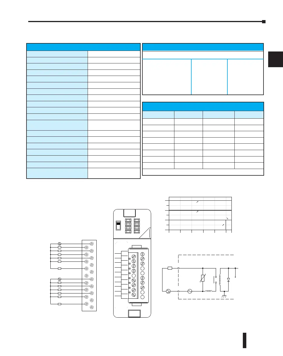
D2–12TR, Relay Output
A
B
5- -240V AC
1.5A 50/60H z
D2-- 12T R
OUT RE LA Y
D2--12TR
0
1
2
3
4
5
CA
4
5
CB
4
5
3
2
1
0
3
2
1
0
5--30V DC
0
4
8
12
Points
COM
OUTP UT
To L E D
Internal module circuitry
4A
5--240 VAC
L
5--30 VDC
0.5A / P t.
0 10 20 30 40 50 55
Ambient Temperature (˚C/˚F )
32 50 68 86 104 122 131
C˚
F˚
1.5A / P t.
0.75A / P t.
5mA- -1.5A
0
1
2
3
5
NC
NC
NC
0
1
2
3
CB
4
5
NC
NC
CA
4
L
L
L
L
L
L
L
L
L
L
L
L
5-- 240 VAC
5-- 30 VDC
5-- 240 VAC
5-- 30 VDC
1.25A / P t.
Derating Chart
D2-12TR Relay Output
Outputs per Module
1
2
Outputs Points Consumed
16 (four unused, see chart below)
Commons per Module
2
(6-pts. per common)
Output Type
Relay, form A (SPST)
Operating Voltage
5-30 VDC; 5-240 VAC
Peak Voltage
30 VDC; 264 VAC
ON Voltage Drop
N/A
AC Frequency
47 to 60 Hz
Minimum Load Current
5 mA @ 5VDC
Max Load Current (resistive)
1.5 A/point; Max of 3A/common
Max Leakage Current
0.1 mA @ 265 VAC
Max Inrush Current
Output: 3A for 10 ms
Common: 10A for 10 ms
Base Power Required 5VDC
450 mA
OFF to ON Response
10 ms
ON to OFF Response
10 ms
Terminal Type (included)
Removable; D2-16IOCON
Status Indicator
Logic side
Weight
4.6 oz. (130g)
Fuses
(2) 4A slow blow, replaceable
Order D2-FUSE-4 (5 per pack)
Typical Relay Life (Operations)
Voltage/Load Current Closures
24 VDC Resistive 1A 500k
24 VDC Solenoid 1A 100k
110 VDC Resistive 1A 500k
110 VDC Solenoid 1A 200k
220 VAC Resistive 1A 350k
220 VAC Solenoid 1A 100k
Addresses Used
Points Used? Points Used?
Yn+0 Yes Yn+10 Yes
Yn+1 Yes Yn+11 Yes
Yn+2 Yes Yn+12 Yes
Yn+3 Yes Yn+13 Yes
Yn+4 Yes Yn+14 Yes
Yn+5 Yes Yn+15 Yes
Yn+6 No Yn+16 No
Yn+7 No Yn+17 No
n is the starting address

 Loading...

