Network Slave Operation
This section describes how other devices on a network can communicate with a CPU port
that you have configured as a DirectNET slave (DL240/250–1/260) or Modbus slave
(DL250–1, DL260). A Modbus host must use the Modbus RTU protocol to communicate
with the DL250–1 or DL260 as a slave. The host software must send a Modbus function
code and Modbus address to specify a PLC memory location the DL250–1 or DL260
comprehends. The DirectNET host uses normal I/O addresses to access applicable DL205
CPU and system. No CPU ladder logic is required to support either Modbus slave or
DirectNET slave operation.
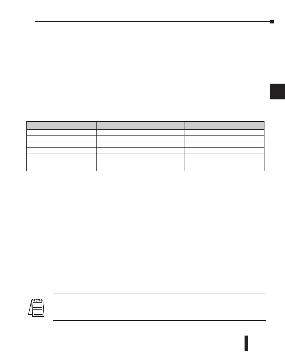
Modbus Function Codes Supported
The Modbus function code determines whether the access is a read or a write, and whether to
access a single data point or a group of them. The DL250–1 and DL260 support the Modbus
function codes described below.
Determining the Modbus Address
There are typically two ways that most host software conventions allow you to specify a PLC
memory location. These are:
• By specifying the Modbus data type and address
• By specifying a Modbus address only.
If Your Host Software Requires the Data Type and Address
Many Host software packages allow you to specify the Modbus data type and the Modbus
address that corresponds to the PLC memory location. This is the easiest method, but not all
packages allow you to do it this way.
The actual equation used to calculate the address depends on the type of PLC data you are
using. The PLC memory types are split into two categories for this purpose.
• Discrete – X, SP, Y, C, S, T (contacts), CT (contacts)
• Word – V, Timer current value, Counter current value
In either case, you basically convert the PLC octal address to decimal and add the appropriate
Modbus address (if required). The following table shows the exact equation used for each
group of data.
NOTE: For information about the Modbus protocol see www.Modbus.org and select Technical Resources.
For more information about the DirectNET protocol, order our DirectNET User Manual, DA-DNET-M, or
download the manual free from our website: www.automationdirect.com. Select Manuals/Docs>Online User
Manuals>Misc.>DA-DNET-M
DL205 User Manual, 4th Edition, Rev. B
Chapter 4: System Design and Configuration
1
2
3
4
5
6
7
8
9
10
11
12
13
14
A
B
C
D
Modbus Function Code Function DL205 Data Types Available
01 Read a group of coils Y, C, T, CT
02 Read a group of inputs X, SP
05 Set / Reset a single coil (slave only) Y, C, T, CT
15 Set / Reset a group of coils Y, C, T, CT
03, 04 Read a value from one or more registers V
06 Write a value into a single register (slave only) V
16 Write a value into a group of registers V
4–35

 Loading...

