Chapter 2: Installation, Wiring and Specifications
2–6
DL205 User Manual, 4th Edition, Rev. B
Panel Mounting and Layout
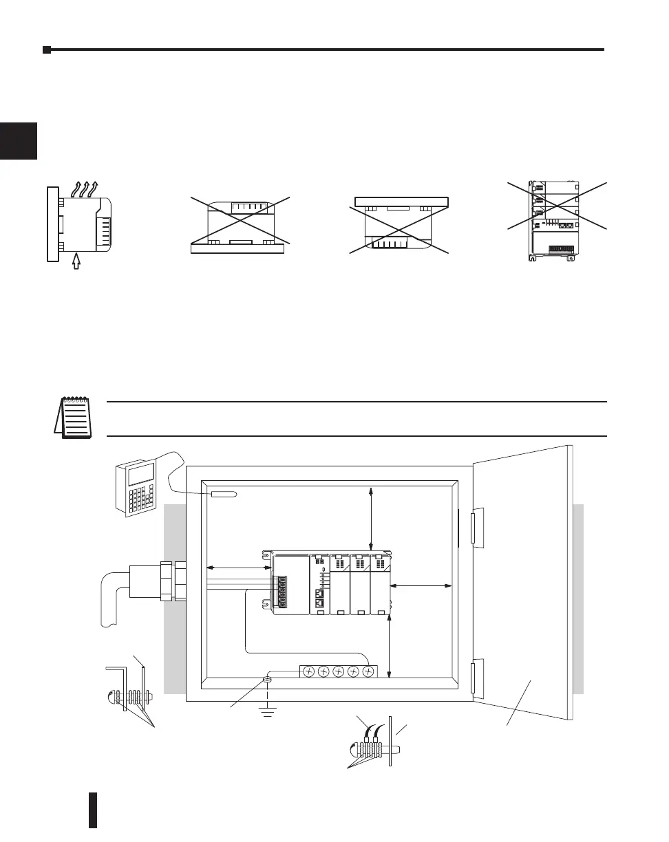
It is important to design your panel properly to help ensure the DL205 products operate
within their environmental and electrical limits. The system installation should comply with
all appropriate electrical codes and standards. It is important the system also conforms to the
operating standards for the application to insure proper performance. The diagrams below
reference the items in the following list.
1. Mount the bases horizontally to provide proper ventilation.
2. If you place more than one base in a cabinet, there should be a minimum of 7.2” (183mm)
between bases.
3. Provide a minimum clearance of 2” (50mm) between the base and all sides of the cabinet. There
should also be at least 1.2” (30mm) of clearance between the base and any wiring ducts.
4. There must be a minimum of 2” (50mm) clearance between the panel door and the nearest DL205
component.
NOTE: The cabinet configuration below is not suitable for EU installations.
Refer to Appendix I European Union Directives.
1
2
3
4
5
6
7
8
9
10
11
12
13
14
A
B
C
D
Safety Guidelines
Earth Ground
Panel Ground
T
erminal
DL205 CPU Base
Power
Source
Temperature
Probe
Star Washers
Panel
Ground Braid
Copper Lugs
Panel or
Single Point
Ground
Star Washers
BUS Bar
Note: there is a minimum of 2” (50mm)
clearance between the panel door
or any devices mounted in the panel door
2”
50mm
min.
2”
50mm
min.
and the nearest DL205 component
2”
50mm
min.
2”
50mm
min.

 Loading...

