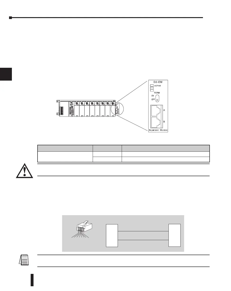
D2–EM Local Expansion Module
The D2–EM expansion unit is attached to the right side of each base in the expansion
system, including the local CPU base. (All bases in the local expansion system must be the
new (–1) bases). The D2–EMs on each end of the expansion system should have the TERM
(termination) switch placed in the ON position. The expansion units between the endmost
bases should have the TERM switch placed in the OFF position. The CPU base can be
located at any base position in the expansion system. The bases are connected in a
daisy–chain fashion using the D2–EXCBL–1 (category 5 straight–through cable with RJ45
connectors). Either of the RJ45 ports (labelled A and B) can be used to connect one
expansion base to another.
The status indicator LEDs on the D2–EM front panels have specific functions which can
help in programming and troubleshooting.
WARNING: Connect/disconnect the expansion cables with the PLC power turned OFF in order for the
ACTIVE indicator to function normally.
D2–EXCBL–1 Local Expansion Cable
The category 5 straight–through D2–EXCBL–1 (1m) is used to connect the D2–EM
expansion modules together. If longer cable lengths are required, we recommend that you
purchase a commercially manufactured cable with RJ45 connectors already attached. The
maximum total expansion system cable length is 30m (98ft.). Do not use Ethernet hubs to
connect the local expansion network together.
NOTE: Commercially available Patch (Straight–through) Category 5, UTP cables will work in place of the
D2–EXCBL–1. The D2–EM modules only use the wires connected to pins 3 and 6 as shown above.
DL205 User Manual, 4th Edition, Rev. B
4–12
Chapter 4: System Design and Configuration
1
2
3
4
5
6
7
8
9
10
11
12
13
14
A
B
C
D
D2–EM Indicator Status Meaning
ACTIVE (Green)
ON D2–EM is communicating with other D2–EM
OFF D2–EM is not communicating with other D2–EM
D2–EXCBL–1 Cable
2
1
3
4
5
6
7
8
34 562187
8-pin RJ45 Connector
(8P8C)
RJ45 RJ45
2
1
3
4
5
6
7
8
GRN
GRN/WHT
GRN
GRN/WHT

 Loading...

