The next step is to make the connections between all devices on the Remote I/O link.
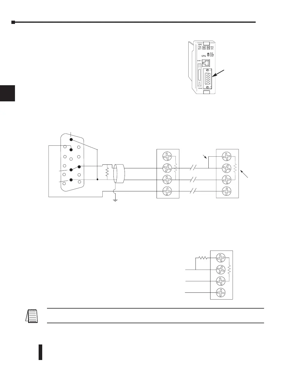
The location of Port 2 on the DL250–1 and DL260 is
on the 15-pin connector , as pictured to the right.
• Pin 7 Signal GND
• Pin 9 TXD+
• Pin 10 TXD–
• Pin 13 RXD+
• Pin 6 RXD–
Now we are ready to discuss wiring the DL250–1 or DL260 to the remote slaves on the
remote base(s). The remote I/O link is a 3-wire, half-duplex type. Since Port 2 of the
DL250–1 and DL260 CPU is a 5-wire full duplex–capable port, we must jumper its transmit
and receive lines together as shown below (converts it to 3-wire, half-duplex).
The twisted/shielded pair connects to the DL250–1 or DL260 Port 2 as shown. Be sure to
connect the cable shield wire to the signal ground connection. A termination resistor must be
added externally to the CPU, as close as possible to the connector pins. Its purpose is to
minimize electrical reflections that occur over long cables. Be sure to add the jumper at the
last slave to connect the required internal termination resistor.
Ideally, the two termination resistors at the cables opposite ends and the cable’s rated
impedance will all match. For cable impedances
greater than 150 ohms, add a series resistor at
the last slave as shown to the right. If less than
150 ohms, parallel a matching resistance across
the slave’s pins 1 and 2 instead. Remember to
size the termination resistor at Port 2 to match
the cables rated impedance.
The resistance values should be between 100 and
500 ohms.
NOTE: To match termination resistance to AutomationDirect L19827 (Belden 9841), use a 120 ohm resistor
across terminals 1 and 2.
DL205 User Manual, 4th Edition, Rev. B
4–28
Chapter 4: System Design and Configuration
1
2
3
4
5
6
7
8
9
10
11
12
13
14
A
B
C
D
DL250–1 / DL260 CPU Port 2
0V
TXD+
TXD–
RXD+
RXD–
TXD+ / RXD+
TXD– / RXD–
Interna
resistor
T
1
2
3
Remote I/O Master
Remote I/O Slave
T
1
2
3
(end of chain)
Remote I/O Slave
T ermination
Resistor
Signal GND
Jumper
Cable: Use AutomationDirect L19954
(Belden 9842) or equivalent
6
7
9
10
13
Internal
150 ohm
resistor
T
1
2
3
Add series
external
resistor
Port 2

 Loading...

