DL205 User Manual, 4th Edition, Rev. B
5–58
Chapter 5: Standard RLL Instructions - Accumulator/Stack Load and Output Data
1
2
3
4
5
6
7
8
9
10
11
12
13
14
A
B
C
D
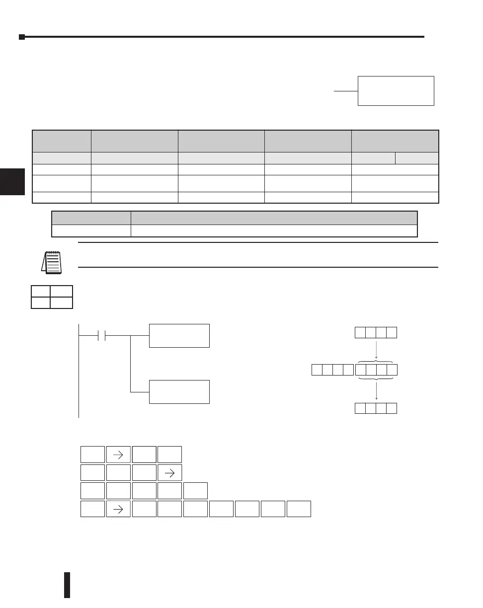
Load (LD)
The Load instruction is a 16-bit instruction that loads the value
(Aaaa), which is either a V-memory location or a 4-digit
constant, into the lower 16 bits of the accumulator. The upper
16 bits of the accumulator are set to 0.
NOTE: Two consecutive Load instructions will place the value of the first load instruction onto the
accumulator stack.
In the following example, when X1 is on, the value in V2000 will be loaded into the
accumulator and output to V2010.
Discrete Bit Flags Description
SP76
On when the value loaded into the accumulator by any instruction is zero.
LD
V2000
X1
Load the value in V2000 into
the lower 16 bits of the
accumulator
OUT
V2010
Copy the value in the lower
16 bits of the accumulator to
V2010
V2010
Acc.
V2000
8935
8935
000089358935
DirectSOFT
The unused accumulator
bits are set to zero
1
B
2
C
0
A
0
A
0
A
ENT
Handheld Programmer Keystrokes
STR
$
ENT
SHFT
ANDST
L
3
D
OUT
GX
SHFT
AND
V
2
C
0
A
1
B
0
A
ENT
Operand Data
Type
DL230 Range DL240 Range DL250-1 Range DL260 Range
A aaa aaa aaa aaa bbb
V-memory V All. See Memory map All. See Memory map All See Memory map All See Memory map
Pointer P –
All V-memory
See Memory map
All V-memory
See Memory map
All V-memory
See Memory map
Constant K 0-FFFF 0-FFFF 0-FFFF 0-FFFF
DS Used
HPP Used

 Loading...

