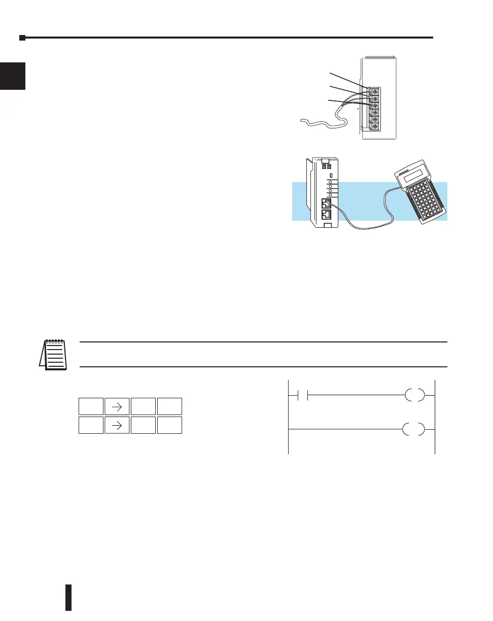
Step 5: Connect the Power Wiring
Connect the wires as shown. Observe all precautions
stated earlier in this manual. For details on wiring see
Chapter 2 Installation, Wiring, and Specifications.
When the wiring is complete, replace the CPU and
module covers. Do not apply power at this time.
Step 6: Connect the Programmer
Either connect the programming cable connected to
a computer loaded with DirectSOFT Programming
Software or a D2-HPP Handheld Programmer
(comes with programming cable) to the top port of
the CPU.
Step 7: Switch On the System Power
Apply power to the system and ensure the PWR
indicator on the CPU is on. If not, remove power
from the system, check all wiring and refer to the troubleshooting section in Chapter 9 for
assistance.
Step 8: Enter the Program
Slide the switch on the CPU to the STOP position (250–1 / 260 only) and then back to the
TERM position. This puts the CPU in the program mode and allows access to the CPU
program. Edit a DirectSOFT program using the relay ladder diagram below and load it into
the PLC. If using an HPP, the PGM indicator should be illuminated on the HPP. Enter the
following keystrokes on the HPP:
NOTE: It is not necessary for you to configure the I/O for this system since the DL205 CPUs automatically
examine any installed modules and establish the correct configuration.
After entering the example program put the CPU in the RUN mode with DirectSOFT or
after entering the program using the HPP, slide the switch from the TERM position to the
RUN position and back to TERM. The RUN indicator on the CPU will come on indicating
the CPU has entered the run mode. If not repeat Step 8 insuring the program is entered
properly or refer to the troubleshooting guide in chapter 9.
During Run mode operation, the output status indicator “0” on the output module should
reflect the switch status. When the switch is on the output should be on.
DL205 User Manual, 4th Edition, Rev. B
1–12
Chapter 1: Getting Started
1
2
3
4
5
6
7
8
9
10
11
12
13
14
A
B
C
D
Y0
X0
END
STR
$
1
B
ENT
OUT
GX
2
C
ENT
Handheld Program Keystrokes

 Loading...

