DL205 User Manual, 4th Edition, Rev. B
5–192
Chapter 5: Standard RLL Instructions - Intelligent I/O
1
2
3
4
5
6
7
8
9
10
11
12
13
14
A
B
C
D
Write to Intelligent Module (WT)
The Write to Intelligent Module instruction writes a block of data
(1 to 128 bytes maximum) to an intelligent I/O module from a
block of V-memory in the CPU. The function parameters are
loaded into the first and second level of the accumulator stack and the accumulator by three
additional instructions. Listed below are the steps necessary to program the Read from
Intelligent module function.
Step 1: Load the base number (0 to 3) into the first byte and the slot number (0 to 7) into the second
byte of the second level of the accumulator stack.
Step 2: Load the number of bytes to be transferred into the first level of the accumulator stack.
(maximum of 128 bytes)
Step 3: Load the intelligent module address which will receive the data into the accumulator. This
parameter must be a HEX value.
Step 4: Insert the WT instruction which specifies the starting V-memory location (Vaaa) where the
data will be written from in the CPU.
Helpful hint: — Use the LDA instruction to convert an octal address to its HEX equivalent
and load it into the accumulator when the hex format is required.
NOTE: Status flags are valid only until another instruction uses the same flag.
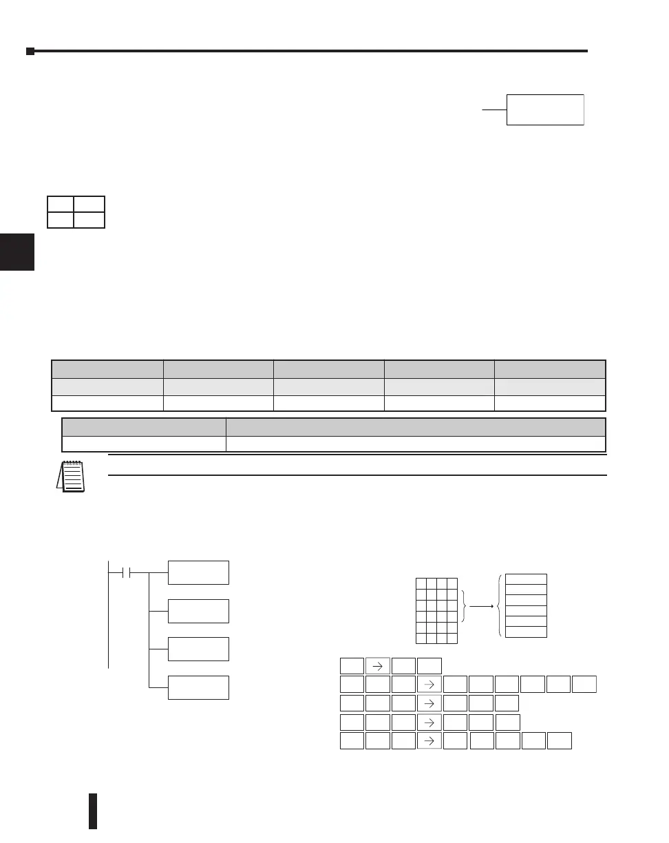
In the following example, when X1 is on, the WT instruction will write six bytes of data to an
intelligent module in base 1, slot 2 starting at address 0 in the intelligent module and copy
the information from Vmemory locations V1400–V1402.
DirectSOFT
Handheld Programmer Keystrokes
LD
K0102
X1
The constant value K0102
specifies the base number
(01) and the base slot
number (02)
LD
K6
The constant value K6
specifies the number of
bytes to be written
LD
K0
The constant value K0
specifies the starting address
in the intelligent module
WT
V1400
V1400 is the starting
location in the CPU where
the specified data will be
written from
V1401
7856
V1402
0190
V1403
XXXX
V1404
XXXX
V1377
XXXX
V1400
3412
Data
12
34
56
78
90
01
Address 0
Address 1
Address 2
Address 3
Address 4
Address 5
CPU Intelligent Module
1
B
ENT
0
A
STR
$
SHFT
ANDST
L
3
D
SHFT
ANDN
W
PREV
4
E
0
A
1
B
0
A
2
C
ENT
6
G
SHFT
ANDST
L
3
D
PREV ENT
0
A
SHFT
ANDST
L
3
D
PREV ENT
MLR
T
1
B
0
A
ENT
Discrete Bit Flags Description
SP54 On when RX, WX, RD, WT instructions are executed with the wrong parameters.
Operand Data Type DL230 Range DL240 Range DL250-1 Range DL260 Range
aaa aaa aaa aaa
V-memory V All (See page 3 - 53) All (See page 3 - 54) All (See page 3 - 55) All (See page 3 - 56)
DS Used
HPP Used

 Loading...

