DL205 User Manual, 4th Edition, Rev. B
5–195
Chapter 5: Standard RLL Instructions - Network
1
2
3
4
5
6
7
8
9
10
11
12
13
14
A
B
C
D
Write to Network (WX)
The Write to Network instruction is used to write a block of data
from the master device to a slave device on the same network. The
function parameters are loaded into the first and second level of
the accumulator stack and the accumulator by three additional
instructions. Listed below are the steps necessary to program the
Write to Network function.
Step 1: Load the slave address (0 to 90 BCD) into the first byte and the PLC internal port (KF1) or
slot number of the master DCM or ECOM (0 to 7) into the second byte of the second level
of the accumulator stack.
Step 2: Load the number of bytes (0 to 128 BCD, multiple of 2) to be transferred into the first level
of the accumulator stack.
Step 3: Load the address of the data in the master that is to be written to the network into the
accumulator. This parameter requires a HEX value.
Step 4: Insert the WX instruction which specifies the starting V-memory location (Aaaa) where the
data will be written to the slave.
Helpful hint: — For parameters that require HEX values, the LDA instruction can be used to
convert an octal address to the HEX equivalent and load the value into the accumulator.
Standard RLL
Instructions
A aaa
WX
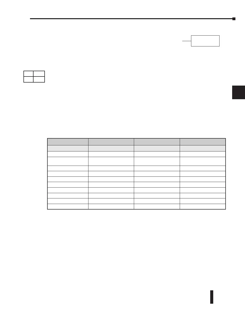
Operand Data Type DL240 Range DL250-1 Range DL260 Range
A aaa aaa aaa
V-memory V All (See page 3 - 54) All (See page 3 - 55) All (See page 3 - 56)
Pointer P
All V-memory
(See page 3 - 54)
All V-memory
(See page 3 - 55)
All V-memory
(See page 3 - 56)
Inputs X 0-477 0-777 0-1777
Outputs Y 0-477 0-777 0-1777
Control Relays C 0-377 0-1777 0-3777
Stage S 0-777 0-1777 0-1777
Timer T 0-177 0-377 0-377
Counter CT 0-177 0-177 0-377
Global I/O GX/GY - - 0-3777
Special Relay SP 0-137 540-617 0-777 0-777
DS Used
HPP Used

 Loading...

