DL205 User Manual, 4th Edition, Rev. B
5–206
Chapter 5: Standard RLL Instructions - Modbus
1
2
3
4
5
6
7
8
9
10
11
12
13
14
A
B
C
D
• Exception Response Buffer: specifies the master memory address where the Exception Response
will be placed (6-bytes in length). See the table on the following page.The exception response buffer
uses 3 words. These bytes are swapped in the MRX/MWX exception response buffer V-memory so:
V-Memory 1 Hi Byte = Function Code Byte (Most Significant Bit Set)
V-Memory 1 Lo Byte = Address Byte
V-Memory 2 Hi Byte = One of the CRC Bytes
V-Memory 2 Lo Byte = Exception Code
V-Memory 3 Hi Byte = 0
V-Memory 3 Lo Byte = Other CRC Byte
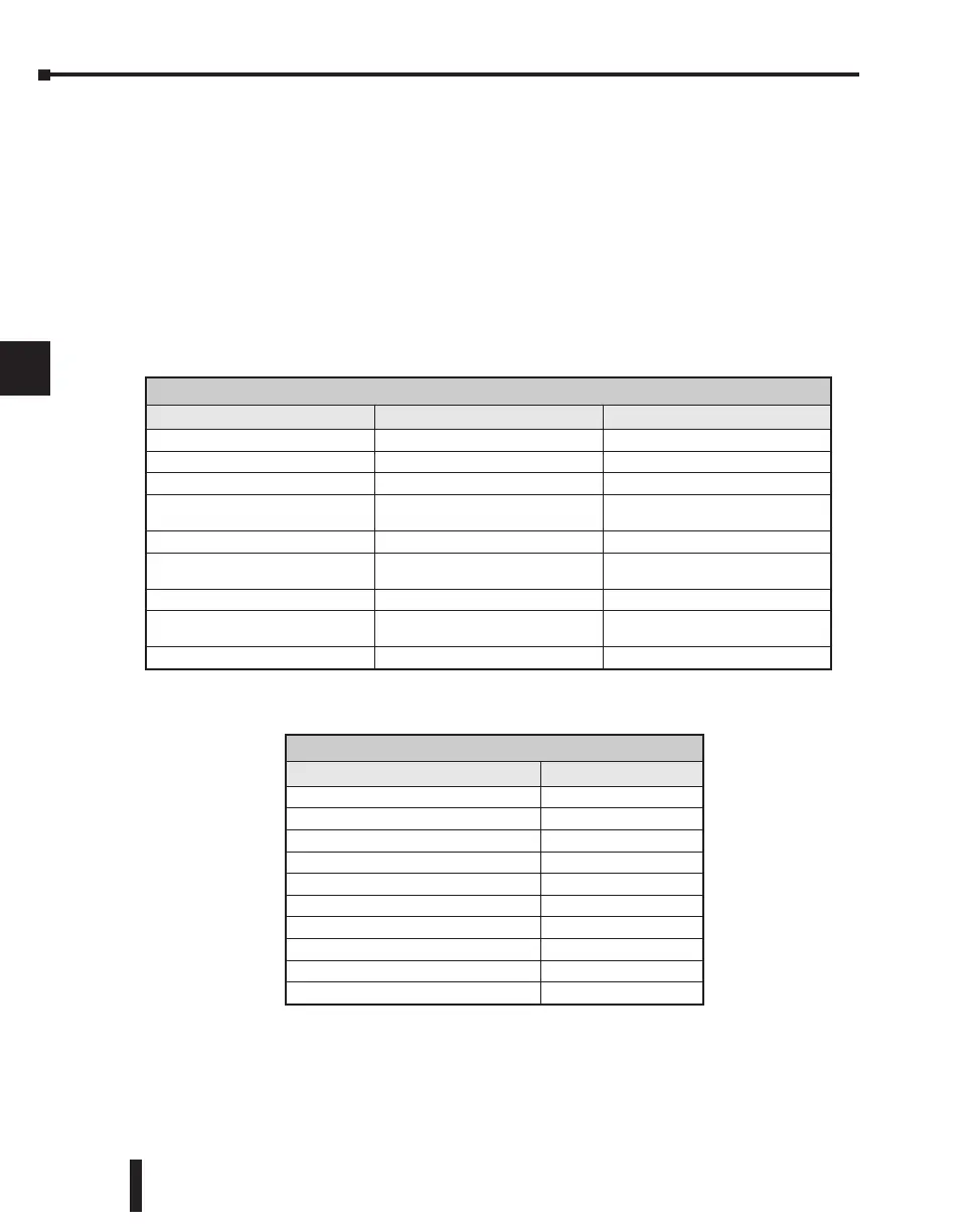
MRX Slave Memory Address
MRX Master Memory Addresses
MRX Slave Address Ranges
Function Code Modbus Data Format Slave Address Range(s)
01-Read Coil 484 Mode 1-999
01-Read Coil 584/984 Mode 1-65535
02-Read Input Status 484 Mode 1001-1999
02-Read Input Status 584/984 Mode
10001-19999 (5 digit) or 100001-
165535 (6 digit)
03-Read Holding Register 484 Mode 4001-4999
03-Read Holding Register 584/984
40001-49999 9 (5 digit) or
4000001-465535 (6 digit)
04-Read Input Register 484 Mode 3001-3999
04-Read Input Register 584/984 Mode
30001-39999 (5 digit) or 3000001-
365535 (6 digit)
07-Read ExceptionStatus 484 and 584/984 Mode n/a
MRX Master Memory Address Ranges
Operand Data Type DL260 Range
Inputs X 0-1777
Outputs Y 0-1777
Control Relays C 0-3777
Stage Bits S 0-1777
Timer Bits T 0-377
Counter Bits CT 0-377
Special Relays SP 0-777
V-memory V all (see page 3-56)
Global Inputs GX 0-3777
Global Outputs GY 0-3777

 Loading...

