DL205 User Manual, 4th Edition, Rev. B
5–210
Chapter 5: Standard RLL Instructions - Modbus
1
2
3
4
5
6
7
8
9
10
11
12
13
14
A
B
C
D
MWX Number of Elements
MWX Exception Response Buffer
MWX Example
DL260 port 2 has two Special Relay contacts associated with it (see Appendix D for comm
port special relays). One indicates “Port busy” (SP116), and the other indicates ”Port
Communication Error” (SP117). The “Port Busy” bit is on while the PLC communicates
with the slave. When the bit is off the program can initiate the next network request. The
“Port Communication Error” bit turns on when the PLC has detected an error. Use of this bit
is optional. When used, it should be ahead of any network instruction boxes since the error
bit is reset when an MRX or MWX instruction is executed.
Typically network communications will last longer than one CPU scan. The program must
wait for the communications to finish before starting the next transaction.
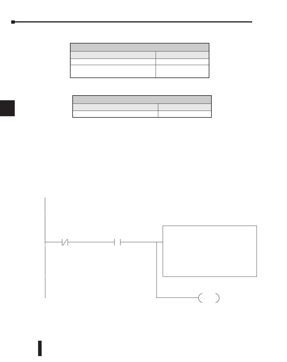
This rung does a Modbus write to the first holding register 40001 of the slave address 1. It will write the
values to V2000. This particular function code only writes to one register. Use Function Code 16 to write
to multiple registers. Only one network instruction (WX, RX, MWX, MRX) can be enabled in each one scan.
That is the reason for the interlock bits. For using many netwo rk instructions on the same port, look at
using the shift register instruction.
SP116
Port 2 Busy Bit
C100
Instruction Interlock Bit
MWX
CPU/DCM Slot:
CPU
Port Number:
Slave Address:
Function Code:
Start Slave Memory Address:
Start Master Memory Address:
Number of Elements:
Modbus Data Type:
Exception Response Buffer:
K2
K1
05 - Force Single Coil
40001
V2000
n/a
584/984 Mode
V400
RST
C100
Instruction Interlock Bit
1
Exception Response Buffer
Operand Data Type DL260 Range
V-memory V all (see page 3-56)
Number of Elements
Operand Data Type DL260 Range
V-memory V all (see page 3-56)
Constant K
Bits: 1-2000
Registers: 1-125

 Loading...

