DL205 User Manual, 4th Edition, Rev. B
2–23
Chapter 2: Installation, Wiring and Specifications
1
2
3
4
5
6
7
8
9
10
11
12
13
14
A
B
C
D
Relay
Coil*
24
VDC
Oscilloscope
* For this example, a 24/290mA/7W
relay is used (AutomationDirect
part no. SC-E03G-24VDC)
60
50
40
30
20
10
0
-10
Volts
Relay
Coil*
24
VDC
Oscilloscope
* For this example, a 24V/125mA/3W
relay is used (AutomationDirect
part no. 750-2C-24D)
45
40
35
30
15
10
0
-5
Volts
25
20
5
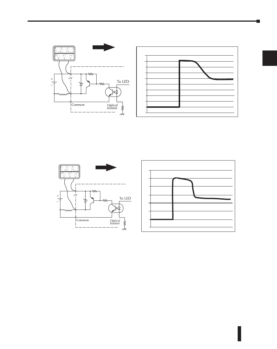
Example: Small Inductive Load with Only Integrated Suppression
The next example uses the same circuit as above, but with a larger 24V/290mA/7W relay,
thereby creating a larger inductive load. As you can see, the transient voltage generated is much
worse, peaking at over 50V. Driving an inductive load of this size without additional transient
suppression is very likely to permanently damage the PLC output.
Example: Larger Inductive Load with Only Integrated Suppression
Additional transient suppression should be used in both these examples. If you are unable to
measure the transients generated by the connected loads of your control system, using
additional transient suppression on all inductive loads would be the safest practice.

 Loading...

