www.balluff.com 17español
8
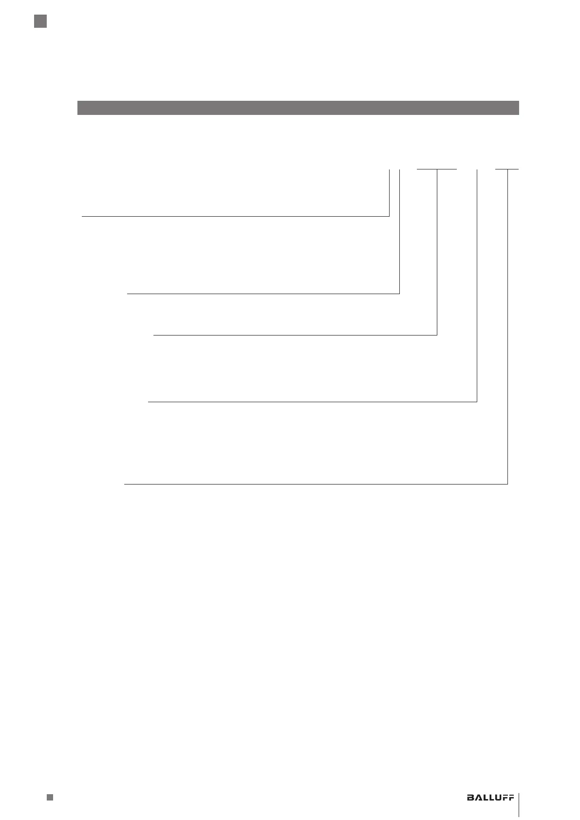
Código de modelo
BTL5 - P1 - M0500 - H - S32
Interfaz:
P = Start/Stop, 2º flanco activo
I = Start/Stop, tri-state, 2º flanco activo
L = Tor
M = Start/Stop, 1er flanco activo
Tensión de servicio:
1 = 20…28VDC
Longitud nominal (4 cifras):
M0500 = indicación métrica en mm, longitud nominal 500mm
(H8/W8: M0025…M1016)
(H/W: M0025…M5500)
Versión de varilla, fijación:
H = rosca de fijación métrica M18×1.5, junta tórica, diámetro de varilla 10,2mm
W = rosca inglesa 3/4"-16UNF, junta tórica, diámetro de varilla 10,2mm
H8 = rosca de fijación métrica M18×1.5, junta tórica, diámetro de varilla 8mm
W8 = rosca inglesa 3/4"-16UNF, junta tórica, diámetro de varilla 8mm
Conexión eléctrica:
S32 = 8 polos, conector M16 según IEC130-9
KA05 = cable 5m, axial (PUR)
K05 = cable 5m, radial (PUR)
BTL5-P/I/L/M1-M ____ -H/W(8) -S32/KA __ /K __
Sistema magnetostrictivo de medición de posición – Forma constructiva de varilla
 Loading...